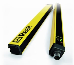
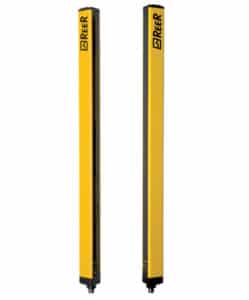
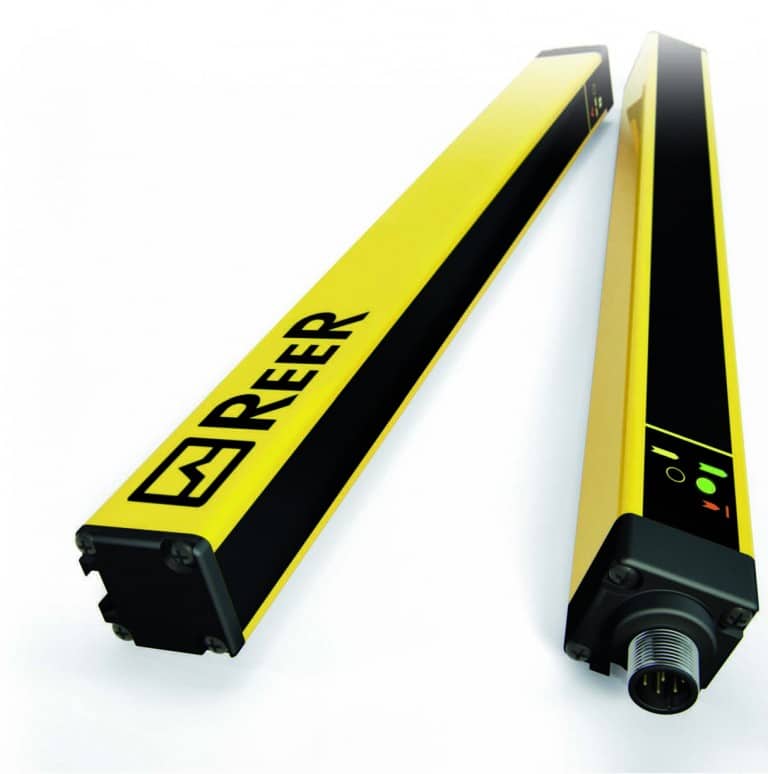
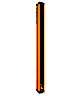
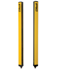
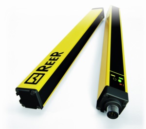
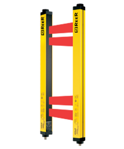
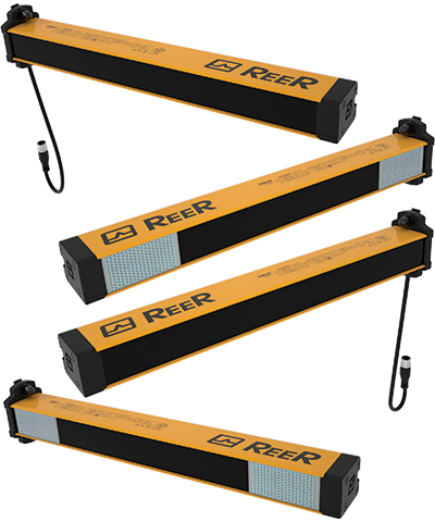
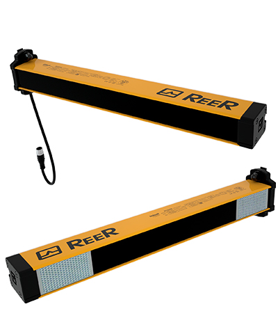
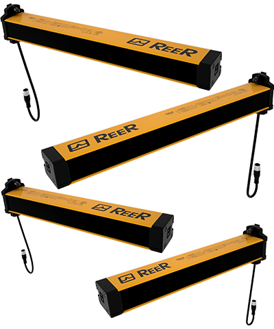
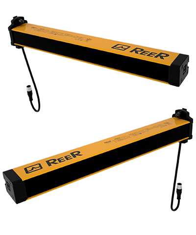
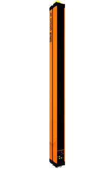
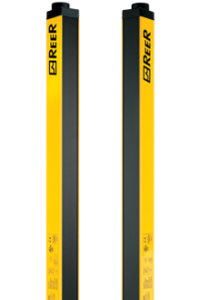
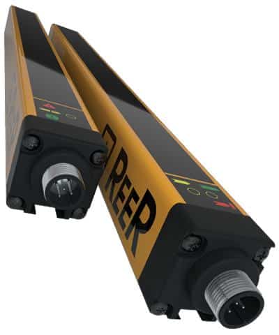
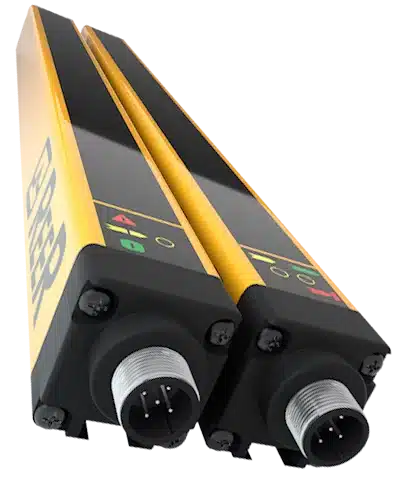
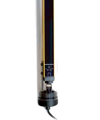
We found 62 results for your search.

Muting Light Curtains. How does Muting Work? Learn NOW.

Overview of light curtains and muting September 26 2024 | Blog Post, Venus Automation As discussed in our two previous blog posts, safety light curtains from ReeR are an effective and innovative method to protect workers from hazardous environments. Light curtains create 2-dimensional planes of infrared beams that project between an emitter and a receiver. Dependent on the application, ReeR offer light curtains that are programmable, and trigger an output signal when a number of beams – consecutive or random – are obstructed. These output signals can then be used as logic input for safety PLCs and relays, such as controllers offered by Wieland and ReeR. For more detail on the general functionality of safety light curtains, read here.    For more specific applications of light curtains, where combinations of consecutive blocked beams are acceptable and do not pose as a hazard, light curtains need to discern what is permissible and what is not. This is where muting light curtains prove their value. Muting is the automated, partial suspension of light curtain beams. Light curtains, such as ReeR’s SAFEGATE, are offered with integrated muting arms. These muting arms can be oriented in either parallel or crossed patterns, such that obstructions of certain dimension/orientation can be recognised as hazardous or not. Onboard the muting arms are photocells, which project between one another to create a mutable area of the light curtain. The muting arm photocells belong to ReeR’s MICRON family of measurement light curtains, which is better explored here.     Muting will occur when the beams aboard the muting arms are blocked, effectively negating any output by the light curtain. This will allow only certain objects to pass through without triggering the light curtain’s safety output signal.    Depending on the automated process, objects passing through a light curtain may be repeatedly entering and exiting: passing back and forth through a light curtains protected area. Therefore, SAFEGATE muting arms are offered in configurations that for one-way and two-way muting. SAFEGATE light curtains from ReeR are also capable of long-range projection of up to 80 metres. Thus, they prove useful in large-scale industrial operations; safeguarding large spans of manufacturing areas without the need for additional light curtain’s in series.  Muting – Parallel or crossed beam? Muting arms onboard ReeR SAFEGATE light curtains, as mentioned before, are offered in either parallel or crossed beam configurations. These differ in that they require different conditions to trigger a muting cycle. A parallel or sequential arrangement of the muting beams triggers a muting cycle when beams are obstructed in a specific sequence. If you were to place muting beams parallel to each other, each one would need to be blocked one after another for the light curtain to recognise it as requiring muting; and its width would not be a factor in this.  Meanwhile, crossed beam muting configurations will only mute an incoming/outcoming object when both beems are blocked simultaneously. When boxes move along a conveyor, a SAFEGATE light curtain with crossed beam muting could be used discern between correctly and irregularly shaped items on the conveyor. Cross muting beams require simultaneous blocking to mute the safety output of the light curtain, and thus the width of the shape passing through the muting arms then becomes important. That means that misoriented objects (which will have an unacceptable width) will not be muted. Crossed beam muting thus adds an extra constraint to when muting will occur, ensuring accuracy, safety, and reliability of an assembly line.  How Cross Beam Muting Works Video Selecting the right light curtain – safety or measurement? It is very easy to be overwhelmed by the sheer number of models and options for safety light curtain, and measurement light curtain offered by ReeR. Though visually and operationally similar, there are some distinct differences in the specific applications each family of light curtain is best suited to.    Measurement Light Curtain (ReeR MICRON): Measurement light curtains from ReeR are highly versatile light curtains for industrial/manufacturing line measurement applications. They come in a variety of sizes (both length, and resolution) to effectively count and dimension objects that pass through it. In automated systems like conveyors and assembly lines, ReeR MICRON can be hardware/software configured to determine if measurements are within tolerance, objects are aligned and oriented correctly, and differentiate between different items on the line. They are offered in varying current and varying voltage output models, and one final model which has 2 antivalent outputs, and the option for programmability. ReeR MICRON measurement light curtains are NOT safety rated.    General Purpose Safety Light Curtain (ReeR EOS2, EOS4): ReeR’s EOS series of safety light curtain are a prolific and popular option for general purpose safeguarding. They come in a variety of sizes and resolutions for finger, hand and body protection (14, 30, 90mm). Furthermore, they are also offered in multi-beam configurations for access control. The EOS series are compact and straightforward to use, but do not feature any advanced control options such as muting. EOS light curtains are offered in safety categorys of Type 2 and Type 4. Thus, scenarios that call for higher standards of safety are well serviced by EOS safety light curtains.    Safety Light Curtain with Muting (ReeR SAFEGATE): ReeR SAFEGATE light curtains, as discussed in this blog, are highly capable, large scale safety light curtains. They are offered in various, often multibeam resolutions for large scale, industrial automation applications. Three of the four SAFEGATE safety light curtain models come native with integration options for muting. In applications such as conveyor belts, SAFEGATE safety light curtains will differentiate between shapes of acceptable dimensions and orientation. SAFEGATE light curtains have long range capabilities, and are well suited to creating long-distance, safeguarded areas that should not be crossed during machine operation.  Reer safegate light curtain models SAFEGATE S SAFEGATE SM SAFEGATE SMO SAFEGATE SMPO Description The SAFEGATE S series of light curtains from ReeR are a more basic, standard option for safety light curtains with muting. They come standrad with Type 4 SIL 3 safety ratings, and feature the most basic form of muting functions, two-sensor muting. The use of the SAFEGATE S is generally used for straightforward safety requirements, such as guarding dangerous areas and access points.  Specifications Voltage: 24V DC Connectivity: M12 12-pin, M12 5-pin Outputs: 2 Static PNP outputs Protected Height(s): 510-1800

Measured Risks, Invisible Barriers: How ReeR Light Curtains Keep You Safe

SAFETY & MEASUREMENT light curtains overview SAFETY September 09 2024 | Blog Post, Venus Automation In manufacturing and automated industries, the criticality of worker safety remains prevalent; and machinery that presents as hazardous during operations thus needs to be safeguarded with boundaries put in place. Even at the best of times, an unknowing factory visitor or a simply zoned out operator who has lost focus is all that it takes for an accident to happen. Thus, ‘out-of-bounds’ areas present as crucial in keeping humans safe around machines to upkeep proper procedure, functionality, and efficiency. This is where light curtains from ReeR come into play. Offered in various configurations for a variety of applications, ReeR light curtains think safety even when humans forget to.    Utilising projection of infrared beams (of which the number and spacing is application-dependent), ReeR light curtains work to change output voltage signals which can then be used as logic inputs for safety PLCs and relays. This technology proves its usefulness in guarding humans from hazardous machinery, creating boundaries, guarding perimeters, and creating conditions that would halt machinery if an unusual object (that does not satisfy the light curtain’s conditions) is detected in an assembly line.    In automated processes, precision measurement is required to accurately detect/verify the profile and position of objects. Whether it be counting and sorting the number of different objects passing through an area such as a conveyor belt, or monitoring the levels of materials/pallets, light curtains prove their value. ReeR products such as the MICRON are light curtains with configurations dedicated to precision measurement and monitoring.    Light Curtains and their use in Industry In industrial and automation applications, light curtains provide a critical layer of safety – and can also be used for precise measurement. In safety, light curtains enable a seamless communication between the operator environment, machines, and safety relays. Utilising the projection (transmission) and reception of infrared beams across a plane of beams, the voltage output of a light curtain can be monitored and use as logical input for safety PLCs. Dependening on the configuration of the light curtain, the spacing of the beams can trigger a safety output (halting of operations), for something as small as a finger to something as large as one’s whole body.  Furthermore, measurement light curtains can be used in counting, dimensioning, and automating robots; such as an AGV (automated guided vehicle) using onboard light curtains to measure heights, distances, and widths to determine its next actions. Measurement light curtains are often found in automated, conveyor style machinery as well; where the light curtains can be used to ensure that items passing through its field are counted, positioned, and oriented correctly.  Key overview of REER LIGHT CURTAINS Purpose and Function ReeR light curtains are crucial for ensuring safety and precision in industrial environments. Concerning the safety of the automated environment, a ReeR light curtain can detect objects the size of fingers, hands, or whole bodies. These light curtains can then be placed at out-of-bounds areas that should not be crossed during machinery operating. Upon detecting an object passing through this boundary, light curtains can then signal for machinery to stop – separating humans from hazards.  Light curtains work on the principle of line-of-sight transmission. With one end of the light curtain projecting (emitter) beams across to the other (the receiver). Each beam constitutes the total voltage reading sent by the receiver via a cable, and blocking these cables will change the voltage output. The simplicity of this voltage change facilitates a rapidly available signal for monitoring via safety PLCs; enabling an effectively instantaneous action in response to a beam being blocked.  Applications ReeR light curtains are offered in several varieties. The EOS series light curtains are compact photoelectric sensors, and are used when space is a premium. Often used for machine guarding, EOS light curtains can monitor the upper, middle, and lower sections of a boundary area. EOS light curtains are also offered in a master-slave configuration, and can thus be run in series and span long distances to create large, safeguarded boundaries. Offered in two degrees of safety categorisation, depending on the application, an EOS light curtain is guaranteed to safely work and, should failure come, it will fail safe.  ReeR’s SAFEGATE series are a family of light curtains that can be operated over large distances – up to 80 metres. SAFEGATE light curtains are often used for their muting functions, which use mounted parallel or crossed beams emitted from ‘muting arms’ to permit certain objects through the light curtain without causing a trip signal. SAFEGATE are highly safe, robust light curtains that are offered in programmable variants, allowing for a customisable light curtain using a computer.    ReeR’s ADMIRAL light curtains are larger units reserved for higher-risk environments, making it suitable for demanding industrial settings. Variants of the Admiral are offered with watertight housings and can operate at long distances (depending on the variant, this is 25 or 80 metres). ReeR Admiral variants offer a dual-beam system, making it ideal for outdoor applications and harsh environments – where the dual beams will reduce the sensitivity of the curtain to avoid false-trips due to outdoor elements such as birds, leaves, and inclement weather.  features Muting: ReeR light curtains such as the SAFEGATE SMO include the option for separately sold muting arms. These muting arms work by projecting either parallel or dual-cross beams, and work with the light curtain to permit objects of certain heights and widths to pass through the light curtains without causing a fault/trip.  Safety Compliance: The majority of ReeR light curtains, such as the SAFEGATE, the Admiral, and the EOS4 are offered at a safety level of Category 4 or PL e. Beam Count/Resolution: ReeR light curtains can be fitted with a variety of beams, the spacing of these beams is offered in a variety of resolutions. Resolution is simply the number of beams there are over a given space, and are what determines the size at which an object will be detected by the light curtain. An example of this includes ReeR’s EOS4, which is offered in resolutions (beam spacings) of 14mm, 30mm, and 90mm.    Programming: Products such as ReeR’s SAFEGATE SMPO are fully programmable. They offer an IDE (integrated development environment), called Safegate Configurator –

Keeping Workers Safe: An Overview of Light Curtains

Understanding Light Curtains: July 5, 2024 | Blog Post, Venus Automation safety first in industrial environments In today’s industrial landscape, worker safety is paramount. By safeguarding personnel during interactions with machinery, businesses can significantly reduce accidents, boost productivity, and improve employee morale. Safety devices like light curtains play a vital role in fostering safe work environments, making them a crucial investment. Light curtains, also known as light guards or safety light curtains, are electronic safety devices used extensively in industrial settings to protect personnel near hazardous machinery or areas. Their functionality is based on the interruption of invisible infrared light beams emitted by a transmitter and received by a receiver unit. how light curtains work TRANSMISSION AND DETECTION: The transmitter unit emits a grid of infrared beams across the area requiring protection. The receiver unit, positioned opposite the transmitter, detects these beams using photodetectors. BEAM INTERRUPTION AND SAFETY RESPONSE: When an object or person enters the detection field and breaks one or more light beams, the receiver detects the disruption. This triggers the safety system’s programmed response, such as stopping or disabling machinery movement within milliseconds. Safety Standards and Compliance: Light curtains are designed and validated according to international safety standards (e.g., ISO 13849, IEC 61496) and local regulations (e.g., AS/NZS 4024 in Australia, EN 61496 in Europe). These standards ensure light guards provide reliable safety functions and meet stringent performance criteria. The transmitter unit emits a grid of infrared beams across the area requiring protection. The receiver unit, positioned opposite the transmitter, detects these beams using photodetectors. When an object or person enters the detection field and breaks one or more light beams, the receiver detects the disruption. This triggers the safety system’s programmed response, such as stopping or disabling machinery movement within milliseconds. Light curtains are designed and validated according to international safety standards (e.g., ISO 13849, IEC 61496) and local regulations (e.g., AS/NZS 4024 in Australia, EN 61496 in Europe). These standards ensure light guards provide reliable safety functions and meet stringent performance criteria. KEY INFORMATION ABOUT LIGHT CURTAINS FUNCTIONALITY SAFETY STANDARDS APPLICATIONS RESOLUTION PROTECTIVE HEIGHT RESPONSE TIME Light curtains detect objects, typically human operators, within their sensing field. A disruption triggers a signal to connected machinery, prompting it to stop or enter a safe state. Light curtains adhere to safety standards like AS 4024.1 and AS/NZS 4024.2019 in Australia, ensuring they meet strict safety requirements. Light curtains are used in various industrial applications where operators need access to machinery or processes that could pose a risk, including:    Automated production lines, Robotic work cells, Presses and stamping machines, Packaging and material handling equipment. Determines the spacing between the light beams. Higher resolutions provide finer detection. Consider Venus Automation’s EOS4 X 14mm light curtain for high-resolution needs. The vertical coverage range of the curtain, ensuring it safeguards the entire hazardous area. Venus Automation offers a wide range of light curtains with various protective heights, including the Admiral AX 90mm series. How quickly the light curtain detects an obstruction and triggers a safety response. For applications requiring exceptionally fast response times, explore the Janus ML TRX light curtains offered by Venus Automation. Light curtains detect objects, typically human operators, within their sensing field. A disruption triggers a signal to connected machinery, prompting it to stop or enter a safe state. Light curtains adhere to safety standards like AS 4024.1 and AS/NZS 4024.2019 in Australia, ensuring they meet strict safety requirements. Light curtains are used in various industrial applications where operators need access to machinery or processes that could pose a risk, including:    Automated production lines, Robotic work cells, Presses and stamping machines, Packaging and material handling equipment. Determines the spacing between the light beams. Higher resolutions provide finer detection. Consider Venus Automation’s EOS4 X 14mm light curtain for high-resolution needs. The vertical coverage range of the curtain, ensuring it safeguards the entire hazardous area. Venus Automation offers a wide range of light curtains with various protective heights, including the Admiral AX 90mm series. How quickly the light curtain detects an obstruction and triggers a safety response. For applications requiring exceptionally fast response times, explore the Janus ML TRX light curtains offered by Venus Automation. Light curtain resolution types muting Some light curtains incorporate advanced features like muting (temporarily disabling the safety function for controlled material passage) and blanking (ignoring specific areas within the detection field). Venus Automation’s SAFEGATE type 4 models by REER are programmable and can be configured for muting functions in various high-risk work environments. Reer Light Curtain, Muting Examples calculation of safety distance The position of the light curtain correlates with the effectiveness of the protection given by the light curtain. For maximum effectiveness, the light curtain must be positioned at a distance that it greater than or equal to the minimum safety distance because this would mean the access to the machine is only possible when any dangerous action by the machine has been ceased. The general formula for safety distance is as follows: S = K * T + C S – Minimum safety distance (mm) K – Approaching speed of the body/ parts of the body (mm/s) T – Total stopping time of the whole machine (s) C – Additional distance (mm) Safety Distance Conclusion Light curtains are a valuable safety tool for industrial environments. By understanding their functionality, benefits, and considerations, you can make informed decisions to safeguard your workforce and create a safer work environment. Looking for Light Curtains? Venus Automation offers a comprehensive selection of light curtains from leading manufacturers to suit your specific needs and safety requirements. Visit our website or contact Click to view product Range Safegate MAL 2P TRX Safegate MAT 4P TRX Safegate MAT2X Safegate MAL2X Safegate MZL 2XP Safegate MZT 4P Safegate SMO Safegate SM Safegate SMPO Admiral AX EOS2

Wieland Eco-System

Unifying Automation with Wieland Solutions: A Comprehensive Overview September 02 2024 | Blog Post, Venus Automation The Wieland ecosystem offers a comprehensive suite of automation products that work in perfect synergy to drive efficiency, safety, and innovation. From advanced safety relays to intuitive HMI touch panels, the Wieland ecosystem is engineered to ensure seamless communication between all system components, creating an integrated environment where machines and controls operate in unison. This blog highlights the power of Wieland’s automation solutions, showcasing how their diverse range of products—from safety PLCs to expansion modules—are designed to meet the evolving demands of industrial environments. Explore how the Wieland ecosystem enhances operational control, streamlines processes, and prioritizes safety to transform your automation systems into efficient, cohesive units Wieland Safety PLCs SamosPRO Expansion Module Wieland Safety Relay Safety Relay Expansion Module Wieland Touch Panel Wieland Memory Card Wieland Connection Cables Wieland Safety PLCs Wieland Safety PLCs When it comes to safeguarding your automation processes, Wieland’s range of Safety PLCs offers unparalleled reliability and functionality. Designed to handle critical safety functions and integrate seamlessly with other system components, these PLCs are essential for creating a robust and secure automation environment. Wieland samos PRO SP-COP1 The samos PRO SP-COP1 is a crucial component for extending the functionality of the samos® PRO Compact system. This safety controller is equipped with advanced communication capabilities, enabling it to seamlessly integrate with other automation devices and systems. It supports a variety of safety functions, from emergency stops to safety gates, and ensures that these functions are managed efficiently. By incorporating the SP-COP1 into your setup, you enhance the flexibility and scalability of your safety infrastructure. Wieland samos SP-COP2 Safety Controller The samos SP-COP2 is an advanced safety controller designed for more demanding applications. Its high-performance features include expanded I/O options and enhanced diagnostic capabilities, making it suitable for complex safety systems. The SP-COP2 integrates smoothly with existing samos® PRO systems and offers additional functionalities that cater to evolving industrial needs. Its robust design ensures that safety functions are maintained even under challenging conditions, providing peace of mind and reliability. Model Safety Applications Features Supply Voltage Ordering Code SP-COP2-EN-A Safety control, muting Ethernet for Programming only 24VDC R1.190.1210.0 SP-COP2-ENI-A Safety control, muting, monitoring, HMI Industrial Ethernet (Ethernet/IP, Profinet, MODBUS/TCP) 24VDC R1.190.1310.0 SP-COP2-EN-P-A Safety control, muting, presses, analogue input Ethernet, press/analogue library 24VDC R1.190.1230.0 SP-COP2-ENI-P-A Safety control, muting, monitoring, HMI, presses, analogue input Industrial Ethernet, press/analogue library 24VDC R1.190.1330.0 Wieland SP-SDI Series: Input and Output Expansion Modules Enhance safety PLC systems with up to 12 expansion modules for increased inputs/outputs. Explore SP-SDI input module options for samos® PRO safety systems. Expansion modules can be added to existing samos® PRO and samos® PRO compact systems to provide an increased number of safe inputs and outputs for any safety system. A maximum of 12 modules can be connected to the main CPU via the safety bus connections inbuilt into each module. The SP-SDI input module provides more safe inputs into the samos® PRO safety system. Model Product Number Supply Voltage Outputs and Inputs SP-SDI8-P1-K-A R1.190.0050.0 24 VDC 8 Safe Inputs SP-SDI08-P1-K-A R1.190.0030.0 24 VDC 8 Safe Inputs 4 Solid State Outputs Wieland Samos Communication Expansion Modules With the samos® pro gateways, system information can be transferred between the samos® pro safe control and an industrial control, a visualization system, or a PC. All Gateways: Have bidirectional communication Able to transfer 50 bytes of data Have simple configuration with samos PLAN6   Model Product Number Connection Type Supply Voltage Image SP-CANopen R1.190.0210.1 CANopen with extended diagnosis 24 VDC SP-PROFIBUS-DP R1.190.0190.1 PROFIBUS DP with extended diagnosis 24 VDC SP-EN-ETC R1.190.0160.0 ETHERCAT 24 VDC   Wieland SP-SA Series | Safety Analogue Input Expansion Modules Enhance Safety Systems with Analogue Input Expansion Modules for samos® PRO & PRO Compact. Add up to 12 modules for more safe inputs & outputs. Analogue expansion modules can be added to existing samos® PRO and samos® PRO compact systems to provide an increased number of safe inputs and outputs for any safety system. A maximum of 12 modules can be connected to the main CPU via the safety bus connections inbuilt into each module. All SP-SA Modules have: – 4 safe analog inputs – Galvanic isolation – Limits monitoring – Mathematical functions – Scaling   Model Product Number Inputs Supply Voltage Terminals SP-SAR4-A R1.190.1610.0 4 safe RTD Inputs 24 VDC Screw Terminals SP-SAR4-C R1.190.1620.0 4 safe RTD Inputs 24 VDC Push-in Terminals SP-SAC4-A R1.190.1630.0 4 safe 0-20mA Current Inputs 24 VDC Screw Terminals SP-SAC4-C R1.190.1640.0 4 safe 0-20mA Current Inputs 24 VDC Push-in Terminals SP-SACR22-A R1.190.1650.0 2 safe RTD, Inputs 2 safe 0-20mA Current Inputs 24 VDC Screw Terminals SP-SACR22-C R1.190.1660.0 2 safe RTD, Inputs 2 safe 0-20mA Current Inputs 24 VDC Push-in Terminals TIme Delay Relay Two-Hand Safety Relay Standstill Monitoring and Timer Relay Standalone Safety Relay Wieland SNV 4076SL-A | Time Delay Relay Wieland SNV 4076SL-A The SNV 4076SL-A safety relay offers multiple time-delay variations, providing flexible options for safe control in industrial settings. It supports off-delay times of 0-3 seconds, 0-30 seconds, or 0-300 seconds, making it adaptable to different application needs. Additionally, the relay is available in two power configurations: 24 VDC and 115-230 V AC, allowing it to fit into various voltage environments. Included is an option for either a screw terminal with the SNV 4076SL-A or a push-in terminal with the SNV 4076SL-C. Part Number Ordering Code Outputs Terminals Supply Voltage SNV 4076SL-A R1.188.2040.0 3NO+1NC, 3NO Off-delay 0-3 seconds, 230VAC 6A Screw Terminal 24VDC R1.188.2220.0 115 – 230 V AC R1.188.2070.0 3NO+1NC, 3NO Off-delay 0-30 seconds, 230VAC 6A 24VDC R1.188.2250.0 115 – 230 V AC R1.188.2100.0 3NO+1NC, 3NO Off-delay 0-300 seconds, 230VAC 6A 24VDC R1.188.2280.0 115 – 230 V AC SNV 4076SL-C R1.188.2050.0 3NO+1NC, 3NO Off-delay 0-3 seconds, 230VAC 6A Push-in Terminal 24VDC R1.188.2230.0 115 – 230 V AC R1.188.2080.0 3NO+1NC, 3NO Off-delay 0-30 seconds, 230VAC 6A 24VDC R1.188.2260.0 115 – 230 V AC R1.188.2110.0 3NO+1NC, 3NO Off-delay 0-300 seconds, 230VAC 6A 24VDC R1.188.2290.0 115 – 230

Guardians of the Machine: How samosPRO Keeps Your Factory Safe

Weiland Samos PRO PLC August 9, 2024 | Blog Post, Venus Automation The Core of Safety systems Safety systems in industrial environments are essential for protecting workers, machinery, and the environment from hazards. These systems typically include safety controllers, relays, sensors, switches, and actuators that monitor and control safety functions like emergency stops, interlock,  monitoring, and speed control. They ensure compliance with safety standards, enabling quick responses to unsafe conditions through communication and diagnostic interfaces. Commonly used in industries like manufacturing and automotive, these systems are integrated into broader automation frameworks to maintain safety and operational efficiency. The samos® PRO is programmed using the intuitive and license-free samos® PLAN 6 software, which includes features for automatic hardware configuration, integrated simulation, and comprehensive function block libraries certified by TÜV. This makes it ideal for ensuring functional safety in various industrial applications Operations of the Samos controller: 1. Input Monitoring The controller continuously monitors inputs from safety devices like emergency stops, light curtains, door switches, and sensors, detecting changes in status such as emergency activations or obstructions. 2. Logic Processing Safety logic is configured using the samos® PLAN 6 software, allowing for the creation of safety functions and sequences with pre-certified function blocks. The logic processes input signals to determine the appropriate safety responses. 3. Output Control The controller activates or deactivates safety outputs based on processed logic, controlling actuators, motors, and other machinery to ensure safe operation. High-power outputs can directly manage safety devices without additional relays. 4. Communication and Diagnostics The controller uses communication gateways (e.g., PROFINET IO, EtherNet/IP, Modbus TCP) to connect with other systems, providing remote access to diagnostic information for monitoring and troubleshooting. On-site diagnostics are aided by LEDs displaying the status of all inputs and outputs. 5. Safety Assurance The system continuously checks for faults, triggering safety responses when issues are detected. It allows simulation of sensor inputs for testing, and real-time validation with oscilloscope functions helps monitor performance and detect irregularities. The controller continuously monitors inputs from safety devices like emergency stops, light curtains, door switches, and sensors, detecting changes in status such as emergency activations or obstructions. Safety logic is configured using the samos® PLAN 6 software, allowing for the creation of safety functions and sequences with pre-certified function blocks. The logic processes input signals to determine the appropriate safety responses. The controller activates or deactivates safety outputs based on processed logic, controlling actuators, motors, and other machinery to ensure safe operation. High-power outputs can directly manage safety devices without additional relays. The controller uses communication gateways (e.g., PROFINET IO, EtherNet/IP, Modbus TCP) to connect with other systems, providing remote access to diagnostic information for monitoring and troubleshooting. On-site diagnostics are aided by LEDs displaying the status of all inputs and outputs. The system continuously checks for faults, triggering safety responses when issues are detected. It allows simulation of sensor inputs for testing, and real-time validation with oscilloscope functions helps monitor performance and detect irregularities. KEY features ABOUT the samos controller: INTUITIVE PROGRAMMING MODULAR DESIGN ADVANCED FEATURES ROBUST AND RELIABLE CONVENIENT DOCUMENTATION Samos® PLAN 6 Software: Intuitive operation through automatic hardware configuration, error-free commissioning with integrated simulation, and logic analysis. Comprehensive Library: Includes TÜV-certified function blocks for various applications like muting, press, analog, and combustion libraries. Flexible Screens: Comfortable machine setup, flexible window arrangements, and customizable layouts for laptops, PCs, and tablets. Expandable I/O: Basic module includes 20 inputs and 4 outputs, expandable up to 116 safe inputs and 52 outputs with additional modules. Communication Gateways: Integrated communication options include PROFINET IO, EtherNet/IP, Modbus TCP, and can be extended with PROFIBUS DP, CANopen, and EtherCAT modules. Forcing Function: Allows simulation of missing sensor hardware, minimizing errors during shift changes and enabling fast troubleshooting. Online Recording: Includes oscilloscope function for real-time validation and long-term recording for troubleshooting. Remote Diagnostics: Global remote diagnostics and access via integrated Ethernet, VPN router, LAN, WLAN, or mobile radio. Advanced Security: Protection against manipulation and unauthorized access, ensuring project integrity and security against hacker attacks.   Temperature Range: Operates in extreme conditions from -25°C to +65°C. High Switching Power: 4A switching power per output, reducing the need for additional relays. Standards Compliance: Meets EN 61508, EN 60204, EN 62061, EN ISO 13849-1, EN 81-20/50, EN 692, EN 693, EN/IEC 61511, EN 50156-1 standards, and is TÜV and cULus approved.   One-Click Report Generation: Simplified project documentation with one-click report generation, including project info, CRC, and safety values (SIL, Kat, PL, PFHd). Samos® PLAN 6 Software: Intuitive operation through automatic hardware configuration, error-free commissioning with integrated simulation, and logic analysis. Comprehensive Library: Includes TÜV-certified function blocks for various applications like muting, press, analog, and combustion libraries. Flexible Screens: Comfortable machine setup, flexible window arrangements, and customizable layouts for laptops, PCs, and tablets. Expandable I/O: Basic module includes 20 inputs and 4 outputs, expandable up to 116 safe inputs and 52 outputs with additional modules. Communication Gateways: Integrated communication options include PROFINET IO, EtherNet/IP, Modbus TCP, and can be extended with PROFIBUS DP, CANopen, and EtherCAT modules. Forcing Function: Allows simulation of missing sensor hardware, minimizing errors during shift changes and enabling fast troubleshooting. Online Recording: Includes oscilloscope function for real-time validation and long-term recording for troubleshooting. Remote Diagnostics: Global remote diagnostics and access via integrated Ethernet, VPN router, LAN, WLAN, or mobile radio. Advanced Security: Protection against manipulation and unauthorized access, ensuring project integrity and security against hacker attacks.   Temperature Range: Operates in extreme conditions from -25°C to +65°C. High Switching Power: 4A switching power per output, reducing the need for additional relays. Standards Compliance: Meets EN 61508, EN 60204, EN 62061, EN ISO 13849-1, EN 81-20/50, EN 692, EN 693, EN/IEC 61511, EN 50156-1 standards, and is TÜV and cULus approved.   One-Click Report Generation: Simplified project documentation with one-click report generation, including project info, CRC, and safety values (SIL, Kat, PL, PFHd). Weiland: Safety controller and Safety PLC Samos Pro compact controllers: SamosPRO Compact Basic SamosPRO Compact Plus The system features a main CPU for managing safety

MOSAIC SAFETY CONTROLLERS: IT’S DOUBLE OR NOTHING

Overview of MOSAIC Safety PLC: August 23 2024 | Blog Post, Venus Automation WHAT classifies as mosaic safety controllers? MOSAIC safety controller typically refers to a system or device used in industrial automation or safety-critical environments to monitor and ensure the safety of operations involving machines or processes. MOSAIC safety controllers are considered a unique safety device due to its ability to control and manage multiple safety functions for single or multiple machines simultaneously. This function can be attributed to ability to be easily expandable, configured and modular design. MOSAIC expansion units are components designed to extend the capabilities of MOSAIC safety PLCs (Programmable Logic Controllers). These expansion units provide additional inputs and outputs (I/O) to the base MOSAIC PLC, allowing for more complex and larger-scale safety control systems. ReeR MOSAIC Series Key features of MOSAIC systems: PURPOSE AND FUNCTION A MOSAIC safety controller is designed to execute various safety functions such as emergency stop, light curtains, safety gates, and safety interlocks. These functions ensure that personnel and equipment are protected from potential hazards. INTEGRATION It integrates with other industrial control systems (such as PLCs – Programmable Logic Controllers) to coordinate safety-related activities with operational tasks. This integration allows for seamless control and monitoring of safety measures across the entire system. APPLICATIONS Manufacturing/ Food Processing – MOSAIC systems are used to monitor safety devices like emergency stops, light curtains, and safety mats, and to control the safety functions of machinery. They help prevent accidental machine starts, reduce risks during setup and maintenance, and stop operations when a hazard is detected. Automation Industry – MOSAIC systems help manage multiple safety inputs like emergency stops, safety scanners, and door locks, ensuring the safe shutdown of machinery and robots in case of any hazards. COMPLIANCE AND STANDARDS MOSAIC safety controllers adhere to international safety standards such as ISO 13849, IEC 61508 and AS4023.2019. These standards define the requirements for the design, implementation, and validation of safety-related systems to ensure reliability and effectiveness in safeguarding personnel and assets. PROGRAMMING AND CONFIGURATION MOSAIC safety controllers typically have user-friendly programming interfaces or software tools for configuring safety functions, defining safety zones, and setting parameters related to safety performance. SYSTEM DIAGNOSIS Fault Tolerance: They often incorporate features for fault tolerance and diagnostic capabilities to detect and respond to faults or failures within the safety system promptly.   Monitoring and Reporting: They provide real-time monitoring of safety conditions and may generate reports or alerts in case of safety breaches or anomalies. This helps in maintaining a high level of safety awareness and operational efficiency.   Scalability: Depending on the application, MOSAIC safety controllers may need to support scalability, allowing for expansion or modification of safety functions as operational requirements change. A MOSAIC safety controller is designed to execute various safety functions such as emergency stop, light curtains, safety gates, and safety interlocks. These functions ensure that personnel and equipment are protected from potential hazards. It integrates with other industrial control systems (such as PLCs – Programmable Logic Controllers) to coordinate safety-related activities with operational tasks. This integration allows for seamless control and monitoring of safety measures across the entire system. Manufacturing/ Food Processing – MOSAIC systems are used to monitor safety devices like emergency stops, light curtains, and safety mats, and to control the safety functions of machinery. They help prevent accidental machine starts, reduce risks during setup and maintenance, and stop operations when a hazard is detected. Automation Industry – MOSAIC systems help manage multiple safety inputs like emergency stops, safety scanners, and door locks, ensuring the safe shutdown of machinery and robots in case of any hazards. MOSAIC safety controllers adhere to international safety standards such as ISO 13849, IEC 61508 and AS4023.2019. These standards define the requirements for the design, implementation, and validation of safety-related systems to ensure reliability and effectiveness in safeguarding personnel and assets. MOSAIC safety controllers typically have user-friendly programming interfaces or software tools for configuring safety functions, defining safety zones, and setting parameters related to safety performance. Fault Tolerance: They often incorporate features for fault tolerance and diagnostic capabilities to detect and respond to faults or failures within the safety system promptly.   Monitoring and Reporting: They provide real-time monitoring of safety conditions and may generate reports or alerts in case of safety breaches or anomalies. This helps in maintaining a high level of safety awareness and operational efficiency.   Scalability: Depending on the application, MOSAIC safety controllers may need to support scalability, allowing for expansion or modification of safety functions as operational requirements change. mosaic safety designer (MSD) SOftware: The MOSAIC safety relays come with a complementary software from ReeR used for configuring the safety relays and designing complex systems and then simulating the output which will be integral for faultless safety system. The ReeR Safety Designer software is designed to be easy to use and full of functional blocks that contain different safety equipment to be flexible with designing a wide range of safety systems. Furthermore, the I/O monitor allows for monitoring of all I/O’s of any designed safety system in real-time. The flexibility and simplicity of the designing complex safety systems can be attributed to the different available terminal blocks for a range of safety devices found in the MOSAIC Safety Designer. ReeR MSD Software: Guard Lock System Schematic operational Scenario: Guard lock System A guard lock is present to prevent unauthorized access to a saw machine during the machine’s progress. A safety system is designed to monitor the speed of the tool. Guarding Lock Mechanism Access Control Safety Interlocks Operator Panel This is a safety feature that physically locks the door or access point to a hazardous area when the associated machinery is operating at normal speed. This prevents unauthorized access and ensures safety during operation. Normal Operation: Access to the hazardous area is restricted while the machinery is running at normal speed. The guard lock remains locked.   End of Cycle or Access Request: Access is permitted either after the machine’s working cycle is complete

4 Facts You HAVE to Know About Wireless Safety Systems

A Brief Overview of Wireless Safety Systems: August 1 2024 | Blog Post, Venus Automation WHAT ARE Wireless Safety systems? Wireless systems can be categorized as a collection of wireless devices that work in uniform together to maximize security for people, property and other assets from any dangerous situation. Wireless systems can be simple as pressing a button to allow someone to enter a door without turning a physical key or on an industrial scale, remotely shutting down systems for any machinery because it started to operate in a dangerous manner without having to enter the danger zone and shut it down.  Key overview of wireless safety systems: PURPOSE AND FUNCTION Ensure the safety of individuals and property by detecting and alerting to various hazards or security breaches through the use of wireless communication technologies. TYPES Motion Detectors: Alert you to movement in areas where it’s not expected. Door/Window Contacts: Notify you if a door or window is opened. Smoke and Carbon Monoxide Detectors: Detect dangerous levels of smoke or gas and alert you. Water Leak Detectors: Identify leaks that could lead to flooding or water damage. APPLICATIONS Workplace Safety: Systems for detecting gas leaks, monitoring for fire hazards, and ensuring overall safety compliance. Asset Protection: Wireless surveillance and alarm systems to protect valuable equipment and inventory. Employee Safety: Panic buttons or wearable devices for employees working in potentially hazardous environments or remote locations. COMPLIANCE AND STANDARDS Safety switches help industries comply with safety regulations and standards such as OSHA, IEC, and ANSI. They are essential for maintaining workplace safety and minimizing risks of accidents. INSTALLATION AND MAINTENANCE Ideally installed at locations where there is a risk of a machine fault so any remote control can cut power to the machine. Additional emergency stop and control functions can be implemented wirelessly for more safety.   Regular testing and maintenance are required to ensure they function correctly and meet safety standards. FEATURES Instant Alerts: Sends immediate notifications via audio alarms, SMS, emails, or app notifications to inform users of emergencies or system status. Remote Monitoring: Allows users to receive alerts and monitor system status remotely through smartphones, tablets, or computers. Communication Protocols: Utilizes technologies such as Wi-Fi, Bluetooth, Zigbee, or cellular networks to connect sensors, alarms, and control panels without the need for extensive wiring. Mesh Networking: In some systems, devices form a mesh network to extend coverage and reliability by relaying information between nodes. Simple Setup: Typically easy to install with minimal wiring, often involving just mounting devices and pairing them with a central hub or control panel. Scalability: Easily expandable to add more sensors or devices as needed without extensive reconfiguration. Self-Testing: Periodically tests its own components and sensors to ensure they are functioning correctly and notifies users of any issues. Diagnostic Tools: Provides troubleshooting and diagnostic information to help users identify and resolve problems. Event Logs: Maintains logs of system events, alerts, and actions, which can be reviewed for troubleshooting or auditing purposes. Usage Statistics: Provides data on system usage, including sensor activity and battery status. Ensure the safety of individuals and property by detecting and alerting to various hazards or security breaches through the use of wireless communication technologies. Motion Detectors: Alert you to movement in areas where it’s not expected. Door/Window Contacts: Notify you if a door or window is opened. Smoke and Carbon Monoxide Detectors: Detect dangerous levels of smoke or gas and alert you. Water Leak Detectors: Identify leaks that could lead to flooding or water damage. Workplace Safety: Systems for detecting gas leaks, monitoring for fire hazards, and ensuring overall safety compliance. Asset Protection: Wireless surveillance and alarm systems to protect valuable equipment and inventory. Employee Safety: Panic buttons or wearable devices for employees working in potentially hazardous environments or remote locations. Safety switches help industries comply with safety regulations and standards such as OSHA, IEC, and ANSI. They are essential for maintaining workplace safety and minimizing risks of accidents. Ideally installed at locations where there is a risk of a machine fault so any remote control can cut power to the machine. Additional emergency stop and control functions can be implemented wirelessly for more safety.   Regular testing and maintenance are required to ensure they function correctly and meet safety standards. Instant Alerts: Sends immediate notifications via audio alarms, SMS, emails, or app notifications to inform users of emergencies or system status. Remote Monitoring: Allows users to receive alerts and monitor system status remotely through smartphones, tablets, or computers. Communication Protocols: Utilizes technologies such as Wi-Fi, Bluetooth, Zigbee, or cellular networks to connect sensors, alarms, and control panels without the need for extensive wiring. Mesh Networking: In some systems, devices form a mesh network to extend coverage and reliability by relaying information between nodes. Simple Setup: Typically easy to install with minimal wiring, often involving just mounting devices and pairing them with a central hub or control panel. Scalability: Easily expandable to add more sensors or devices as needed without extensive reconfiguration. Self-Testing: Periodically tests its own components and sensors to ensure they are functioning correctly and notifies users of any issues. Diagnostic Tools: Provides troubleshooting and diagnostic information to help users identify and resolve problems. Event Logs: Maintains logs of system events, alerts, and actions, which can be reviewed for troubleshooting or auditing purposes. Usage Statistics: Provides data on system usage, including sensor activity and battery status. operational steps For most safety systems that are wireless, multiple components work together to form a single operating system. A wireless emergency stop system consists  a radio controlled safety module and a wireless remote control. The safety modules feature three pairs of two-channel safety inputs, which can be used for devices like emergency stops, light curtains, or safety gates. They also include one safety output with three redundant contact paths. Additionally, each module offers eight inputs and outputs for user-defined control functions. For enhanced diagnostics, the modules are equipped with two status semiconductor outputs, an indicator output for signal reception quality, and a USB interface for

Blogs

Safety Products 12July Safety Relays: The Unsung Heroes of Industrial Safety a brief overview of safety relays: June 10 2024 | Blog Post, Venus Automation In the hustle and bustle of industrial workplaces, ensuring the safety… Read More Newsletters 05July Keeping Workers Safe: An Overview of Light Curtains UNDERSTANDING LIGHT CURTAINS: July 5, 2024 | Blog Post, Venus Automation safety first in industrial environments In today’s industrial landscape, worker safety is paramount. By… Read More Newsletters 19June Streamlining EV Electrical Installations. Discover the Power of the Wieland Podis® Flat Cable System wieland podis flat cable system OVERVIEW As the electrical industry continues to evolve, innovations that promise efficiency, reliability, and cost-effectiveness are increasingly essential. The Wieland… Read More Newsletters 13June Understanding the New EU Machinery Regulation No. 2023/1230: A Comprehensive Guide UNDERSTANDING NEW EU MACHINERY REGULATION June 13, 2024 | Blog Post, Venus Automation OVERVIEW The machinery industry in the EU is undergoing a significant transformation… Read More Safety Products 07June Contactors: The foundations of Safety Automation a brief overview of safety contactors: June 07, 2024 | Blog Post, Venus Automation Safety contactors are critical components in industrial automation and safety systems,… Read More What are Programmable Systems, PLC’s and Safety Automation? In today’s rapidly evolving industrial landscape, prioritizing top-notch safety standards is paramount. Programmable systems have emerged as indispensable tools, offering dynamic solutions to intricate safety… Read More Load More

Training

CESE 3 Day Course 1 Day Safety Training Upcoming course on 17-19th September The seminar provides the necessary legal basics and understanding of standards to evaluate the safety of machinery and to design and calculate safety functions. The seminar is a cooperation between SGS-TÜV Saar and Wieland – Venus Automation. It covers the safety aspects of machinery with the focus on electrotechnical aspects. For more detailed information please download our brochure. CONTENTS DURATION TARGET GROUPS REQUIREMENTS SIZE OF SEMINAR CONTACT VDSI POINTS • EU directives, law and standards• Risk assessment according to EN ISO 12100• Functional safety according to EN ISO 13849-1 and -2 • Safety relevant sensory, logical and electrical actors • Realization of safety performance level PL• Verification and Validation of safety systems 3 days.  • Designers • Developers • Service personnel • Safety engineers At least 2 years of experience in design, construction or service of functional safety systems 10 people max.  Email: info@venusautomation.com.au Phone: (02) 8459 7766 The course grants 3 VDSI Points in the section occupational safety 3 DAY SAFETY TRAINING FORM Fill this form Upcoming Course TBA. This course has become very popular due to it’s vast amount of information and value for money. It has been designed to provide basic knowledge on how to make machinery safe. The course has been updated to include the key points of machinery safety with reference to the new WHS legislation and Australian Standard AS4024..1- 2019 Safety of machinery. Venus Machine Safety Training: INTRODUCTION RISK ASSESSMENT GUARDING OUTCOME •  Fundamentals of safety as per AS 4024.2019 (safety of machinery standard). •  Introduction to Workplace Health & Safety Act and Regulations. •  Responsibility of stake holders incl. employers, designers, importers, manufacturers etc. •  WHS Act 2011 and WHS Regulation 2017 •  Risk minimization/risk control •  Introduction to ISO 13849-1 (AS 4024.1503-2014) and Sistema software • Step by step procedure for risk assessment based on real examples.• Introduction to risk assessment using EN ISO 13849 and IEC 62061 Standard. • Introduction to risk reduction using principles of AS 4024.1302-2019 & EN ISO 13849 (Performance level).   • Hierarchy of guarding as per relevant safety legislation. • Hierarchy of controls as per relevant safety legislation. • Type of guards, definitions and examples. • Safety distance as per relevant sections of AS 4024.1302-2019 (safety of machinery standard). • Wiring examples of safety relay with estop, safety guard switch, light curtain for category 2, 3 and 4. • Introduction to programmable safety controller and practical wiring exercise for safety relay with Estop, Light curtain, Guard interlock for Category 2, 3 and 4. • On completion of this training course, attendants will be able to identify hazards, assess risk and come up with risk control measures for machine safety. • Attendants will be confident in selecting right guarding (following hierarchy of guarding) and design correct level of safety circuit to comply with risk category 2, 3 and 4 as per AS 4024.1501-2006 (Machinery Safety Standard) 1 DAY SAFETY TRAINING FORM Fill this form Upcoming course on 17-19th September The seminar provides the necessary legal basics and understanding of standards to evaluate the safety of machinery and to design and calculate safety functions. The seminar is a cooperation between SGS-TÜV Saar and Wieland – Venus Automation. It covers the safety aspects of machinery with the focus on electrotechnical aspects. For more detailed information please download our brochure. CONTENTS DURATION TARGET GROUPS REQUIREMENTS SIZE OF SEMINAR CONTACT VDSI POINTS • EU directives, law and standards• Risk assessment according to EN ISO 12100• Functional safety according to EN ISO 13849-1 and -2 • Safety relevant sensory, logical and electrical actors • Realization of safety performance level PL• Verification and Validation of safety systems 3 days.  • Designers • Developers • Service personnel • Safety engineers At least 2 years of experience in design, construction or service of functional safety systems 10 people max.  Email: info@venusautomation.com.au Phone: (02) 8459 7766 The course grants 3 VDSI Points in the section occupational safety 3 DAY SAFETY TRAINING FORM Fill this form Upcoming Course TBA. This course has become very popular due to it’s vast amount of information and value for money. It has been designed to provide basic knowledge on how to make machinery safe. The course has been updated to include the key points of machinery safety with reference to the new WHS legislation and Australian Standard AS4024..1- 2019 Safety of machinery. Venus Machine Safety Training: INTRODUCTION RISK ASSESSMENT GUARDING OUTCOME •  Fundamentals of safety as per AS 4024.2019 (safety of machinery standard). •  Introduction to Workplace Health & Safety Act and Regulations. •  Responsibility of stake holders incl. employers, designers, importers, manufacturers etc. •  WHS Act 2011 and WHS Regulation 2017 •  Risk minimization/risk control •  Introduction to ISO 13849-1 (AS 4024.1503-2014) and Sistema software • Step by step procedure for risk assessment based on real examples.• Introduction to risk assessment using EN ISO 13849 and IEC 62061 Standard. • Introduction to risk reduction using principles of AS 4024.1302-2019 & EN ISO 13849 (Performance level).   • Hierarchy of guarding as per relevant safety legislation. • Hierarchy of controls as per relevant safety legislation. • Type of guards, definitions and examples. • Safety distance as per relevant sections of AS 4024.1302-2019 (safety of machinery standard). • Wiring examples of safety relay with estop, safety guard switch, light curtain for category 2, 3 and 4. • Introduction to programmable safety controller and practical wiring exercise for safety relay with Estop, Light curtain, Guard interlock for Category 2, 3 and 4. • On completion of this training course, attendants will be able to identify hazards, assess risk and come up with risk control measures for machine safety. • Attendants will be confident in selecting right guarding (following hierarchy of guarding) and design correct level of safety circuit to comply with risk category 2, 3 and 4 as per AS 4024.1501-2006 (Machinery Safety Standard) 1 DAY SAFETY TRAINING FORM Fill this form Testimonials Rodolfo Ligot Line Engineer – CSR Recomended ☆

Safety Relays: The Unsung Heroes of Industrial Safety

A Brief Overview of Safety Relays: June 10 2024 | Blog Post, Venus Automation In the hustle and bustle of industrial workplaces, ensuring the safety of employees is paramount. Accidents can lead to serious injuries, fatalities, and significant downtime. Enter safety relays—specialized devices designed to keep machinery operating safely, creating a secure environment for workers. WHAT ARE SAFETY RELAYS? Safety relays are electromechanical devices that monitor and manage safety-critical inputs and outputs, such as emergency stop buttons and safety sensors. When hazardous conditions are detected, these relays ensure safe responses like stopping machinery. They are essential in various industries including manufacturing, automotive, packaging, and pharmaceuticals. TYPES OF SAFETY RELAYS DUAL CHANNEL SAFETY RELAYS  These safety relays monitor two independent input signals, ensuring redundancy. Both channels must operate correctly for the output to switch, enhancing reliability in safety-critical applications. TIME DELAYED SAFETY RELAYS Featuring adjustable delays, these relays allow for a controlled sequence of operations before activating or deactivating outputs. This is useful when an immediate shutdown could cause damage or additional hazards. FORCE CUIDED SAFETY RELAYS Designed to ensure all contacts in the safety relay switch simultaneously, preventing contact welding or sticking, and enhancing reliability in critical applications. EMERGENCY STOP SAFETY RELAYS Specifically for emergency stop applications, these relays ensure immediate and reliable shutdown of machinery when an emergency stop button is pressed. GUARD MONITORING SAFETY RELAYS These safety relays monitor safety devices like interlock switches or safety gates, ensuring machinery cannot operate when guards are open or bypassed. LIGHT CURTAIN SAFETY RELAYS Interfacing with safety light curtains, these safety relays detect the presence of objects or personnel in hazardous areas, ensuring machinery stops or slows down when the light curtain is interrupted.  These safety relays monitor two independent input signals, ensuring redundancy. Both channels must operate correctly for the output to switch, enhancing reliability in safety-critical applications. Featuring adjustable delays, these relays allow for a controlled sequence of operations before activating or deactivating outputs. This is useful when an immediate shutdown could cause damage or additional hazards. Designed to ensure all contacts in the safety relay switch simultaneously, preventing contact welding or sticking, and enhancing reliability in critical applications. Specifically for emergency stop applications, these relays ensure immediate and reliable shutdown of machinery when an emergency stop button is pressed. These safety relays monitor safety devices like interlock switches or safety gates, ensuring machinery cannot operate when guards are open or bypassed. Interfacing with safety light curtains, these safety relays detect the presence of objects or personnel in hazardous areas, ensuring machinery stops or slows down when the light curtain is interrupted. Wieland SNV 4063KL-A Diagram Time Delay Relays In some cases, an immediate shutdown of machinery could cause damage or create additional hazards. A time delay allows for a controlled and safe shutdown sequence, preventing mechanical damage or product spoilage. Weiland’s SNV 4063KL-A features advanced time delay capabilities with adjustable delays from 0.15 to 3 seconds or 1.5 to 30 seconds, providing the flexibility to customize response times to your specific needs. This ensures your safety measures are precisely tailored to your operations. Wieland SNV 4063KL-A How do safety relays work? Safety relays operate by monitoring inputs from safety devices and evaluating these signals to ensure safe operating conditions. Here’s a breakdown of their functionality: Input Monitoring Signal Evaluation Logic Processing Output Control Continuously monitor signals from safety devices such as emergency stop buttons, guard doors, and light curtains. Assess input signals to determine if operating conditions are safe.  Process input signals using internal logic circuitry to decide if the equipment can operate safely.  If conditions are safe, the relay energizes the output circuitry. If unsafe conditions are detected, it de-energizes the output circuity to stop the machinery.  Continuously monitor signals from safety devices such as emergency stop buttons, guard doors, and light curtains. Assess input signals to determine if operating conditions are safe.  Process input signals using internal logic circuitry to decide if the equipment can operate safely.  If conditions are safe, the relay energizes the output circuitry. If unsafe conditions are detected, it de-energizes the output circuity to stop the machinery.  Safety relays incorporate several advanced features to enhance their effectiveness and reliability. Many safety relays include redundant internal circuits and perform periodic self-checks to ensure proper operation and maintain reliability. They are designed to respond within milliseconds, which helps minimize risks during emergencies. Additionally, advanced relays offer diagnostic features that monitor the status and health of the relay and connected safety devices, aiding in maintenance and troubleshooting. These features collectively ensure that safety relays perform their critical functions reliably and efficiently in industrial environments. practical applications : Safety relays are used in a variety of scenarios to ensure industrial safety. They provide an immediate shutdown of machinery during emergencies through emergency stop functions. For guard monitoring, safety relays ensure that guards or barriers are in place before any operation can proceed. Light curtain monitoring involves detecting personnel or objects in hazardous areas to prevent accidents. Additionally, two-hand control requires the simultaneous operation of two buttons to initiate potentially hazardous actions, ensuring both hands are away from danger and enhancing overall safety. Time – Delayed Safety Relays: In some situations, an immediate shutdown might cause damage or additional hazards. Time-delayed safety relays like Weiland’s SNV 4063KL-A provide customizable delays from 0.15 to 30 seconds, ensuring a controlled and safe shutdown sequence that prevents mechanical damage or product spoilage.   Cutting-Edge Solutions: The DOLD LH 5946 standstill speed monitor is a prime example of innovation in safety relays. It operates without requiring encoder sensors or proximity switches, detecting the standstill of electric motors by measuring the induced EMF. When the EMF approaches zero, it indicates a standstill state and activates the output relay, ensuring safe conditions. conclusion Safety relays are built to withstand industrial environments, providing reliable performance over extended periods. They are easy to install, integrate seamlessly with various safety devices, and comply with international safety standards such as ISO 13849 and IEC 62061. Regular maintenance is essential to keep

IO-Link Safety: What it is and what is means

IO-Link Safety: What it is and what is means April 17, 2024 | Blog Post, Venus Automation The ever-evolving landscape of industrial automation demands robust, flexible, and safe solutions. Enter IO-Link, a communication protocol rapidly transforming how sensors and actuators interact with controllers in manufacturing environments. This blog post dives deep into the world of IO-Link, exploring its core functionalities, its safety extension (IO-Link Safety), and the advantages it brings to modern industrial automation systems. WHAT IS IO-LINK? IO-Link is a communication protocol used in industrial automation enabling efficient communication between sensors, actuators, and controllers in industrial systems. The primary goal of IO-Link is to provide a point-to-point communication interface for smart devices in the field, allowing for seamless integration into the overall control system. IO-Link enables communication between a master device (such as a PLC or controller) and individual sensors or actuators, creating a point-to-point connection. It allows for the exchange of digital data between devices, providing more information and flexibility compared to traditional analogue connections. IO-Link also allows for the configuration and parameterization of connected devices, making it easier to set up and manage automation systems. This protocol supports bidirectional communication, allowing for real-time data exchange, diagnostics, and monitoring of connected devices. A key feature of these IO-Link devices are that they are typically designed for easy integration, and the protocol supports plug-and-play functionality, simplifying the installation and replacement of devices. IO-Link is an international standard (IEC 61131-9), ensuring compatibility between devices from different manufacturers. WHAT IS IO-LINK SAFETY? IO-Link Safety is an extension of the standard IO-Link communication protocol specifically designed for implementing safety-related communication in industrial automation systems. It allows for the integration of safety functions into the IO-Link architecture, enabling the transmission of safety-related data between safety devices and controllers. This extension enhances the flexibility and efficiency of safety solutions in manufacturing environments.   Functional Safety Fieldbus Profiles (FSCP), as standardized in IEC 61784-3, offers the possibility to conduct safe communication via certain communication channels such as backplane buses of a bus terminal. This is called “tunneling”. IO-Link can also be considered as a possible communication channel. However, such a solution is then not fieldbus-independent as expected from IO-Link, but a solution of the respective fieldbus profile and is also managed and accounted for by the corresponding fieldbus organization and not by the IO-Link community. IO-Link Safety, on the other hand, is a fieldbus-independent safe communication profile that is tailored to the needs of IO-Link and standardized in IEC 61139-2. This means that safety devices only have to be developed once and not anew for each fieldbus variant. By adhering to the IO-Link Safety standard, manufacturers ensure interoperability and streamline the development process, ultimately leading to more efficient and cost-effective safety solutions in industrial settings. The architecture of the Io-link System The Safety PLC: The Safety PLC (Programmable Logic Controller) is a dedicated controller responsible for managing and executing safety-related functions in an industrial automation system. It may interact with the IO-Link Safety Master through a fieldbus or another communication interface. Fieldbus with IO-Link Interface: The Fieldbus is the communication network that connects various devices within an industrial automation system. In the context of IO-Link Safety, the Fieldbus includes an IO-Link interface to support communication with IO-Link devices, including both standard IO-Link devices and IO-Link Safety devices. IO-Link Devices: IO-Link devices are standard sensors, actuators, and other industrial devices that communicate over the IO-Link protocol. These devices are part of the broader industrial automation system and can include sensors like proximity sensors, photoelectric sensors, and actuators like valves and motors. Standard IO-Link devices are typically used for non-safety-critical functions in the automation process. IO-Link System Architecture with Safety Components IO-Link Safety Devices: IO-Link Safety devices are specifically designed for safety-critical applications within the industrial automation system. Examples of IO-Link Safety devices include safety light curtains, emergency stop buttons, and safety interlock switches. These devices communicate safety-critical information using the IO-Link Safety protocol, ensuring that the information is transmitted reliably and with a high level of integrity. What can an IO-Link device do that a standard sensor cannot? IO-Link devices supply three types of data: Process data: Condition information that the IO-Link device reads and sends to the IO-Link master or information that the IO-Link master sends to the IO-Link device. Status information is also transmitted in this process. You can thus check whether the process data is valid. Service data: Information that can be written to the IO-Link device or read from the IO-Link device. Event data: Notifications such as error messages, which are sent from the IO-Link device to the IO-Link master as soon as the event occurs. Other Benefits Productivity: IO-Link devices furnish the controller with intricate condition data, offering invaluable insights for maintenance planning. Swift problem identification is facilitated, allowing users to schedule preventative measures promptly. Simplicity: Installation becomes a breeze as standard cables and connectors are all that’s needed. Maintenance is hassle-free, thanks to the ability to monitor systems and tweak settings effortlessly. With IO-Link devices’ error detection feature, pinpointing issues becomes quick and straightforward. Even the replacement process is a cinch, as parameter data is conveniently stored in the controller.

The Ultimate Handbook for Machine and Equipment Safety

The Ultimate Handbook for Machine And Equipment Safety Nov 29, 2023 | Blog Post, Venus Automation There are many types of machines used in the Australian Workplace which have potential hazards that can harm workers. The Work Health and Safety Act (2011) has requirements for Person Conduction Business or Undertaking (PCBU) to manage risks associated with the use of a plant. In this short blog we will look into: 1. What is machine and equipment safety?  2. What are the hazards and risk? 3. What products are available?  What is machine and equipment Safety? The fundamentals of Machine and equipment safety as per AS 4024.1-2014 involves the practices, protocols, and measures implemented to ensure the well-being of individuals and the protection of property when operating or interacting with various types of machinery and equipment. This involves assessing and mitigating potential hazards, providing proper training for operators, implementing safety features, and adhering to established guidelines and regulations. The goal is to minimize the risk of accidents, injuries, or damage associated with the use of machines and equipment in various industries, ranging from manufacturing and construction to healthcare and beyond. “Safety First” – It’s every employers responsibility – Raju Kotecha What are the Hazards?Typical hazards or the dangerous parts of machinery include: In running rollers that ‘draw you in’ Shear points Flying ejected parts Moving parts that can bump and knock Hot and cold surfaces What are risk? Bumping Catching Flying Swarf Cutting Dragging Shearing Crushing Pressured Liquid/Gas What Safety Products are Avaliable? A brief overview of the key products that can be integrated into your safety design to ensure your employee’s safety: Safety Programable Logic Controller (PLC) Known as a safety PLC, is a specialised type of PLC for the safety automation industry, designed to meet the standard of IEC 62061, ISO 13849-1, and IEC 61058. These devices control and monitor different processes and functions of the machine. Thanks to the nature of PLCs, safety functions can be implemented efficiently and in a customized to the user’s need. With pluggable expansion modules, the safety PLC is also adaptive for larger systems. These PLCs can work in conjunction with various safety sensors and mechanical interlocks.     Find out more by viewing Wieland’s SAMOSPRO range and ReeR’s MOSAIC Series. Wieland’s SAMOSPRO ReeR’s Mosaic Wieland – SAMOS® PRO Compact ReeR – Mosaic M1 Range Safety Relays Safety Relays are devices designed for safety applications meeting the requirements of EN 60947-8-5-1 and EN60204-1. Their primary function is to monitor and manage safety-related processes, acting as a dependable intermediary to execute crucial functions like emergency shutdowns. The relay must met the safety requirement of the circuit having self-monitoring redundancy and must ‘fail-safe’. These devices work in conjunction to safety sensors and interlocks. They are expansion modules available for additional inputs and outputs.   Find out more by viewing our various types of safety relays:   Standalone Safety Relays with 2 N/O Outputs Standalone Safety Relays with 3 N/O Outputs Standalone Safety Relays with 4 N/O Outputs Back EMF Monitoring Relay 2 N/O Outputs 3 N/O Outputs 4 N/O Outputs Back EMF Standstill Monitoring and Timer Relays Time Delay Relays 2 Hand Relays Expansion Modules StandStill Monitoring Time Delay 2-Hand Expansion Modules SNO 4062K-A UF 6925 – SAFEMASTER SR E4 SNE 4028S-A SNE 1 SNA 4044K-A SNV 4052K-A SNE 4024K-A SNV 4063KL-A Safety Light CUrtain Safety Light curtains are a optoelectronic sensor system that uses one or more light beams, emitted by an Emitter and received by a Receiver, to create an array of light breams across an opening or a perimeter. The light curtains will detect the presence or intrusion of objects or people within the defined space, triggering a safety response, such stopping the machine. These devices are made to met the requirement of IEC 61496-1 and IEC 61496-2. Find out more about our wide range of  Light Curtains below:   Finger Protection (14mm) Hand Protection (30mm) Body Protection (90mm) Multi-beam – Perimeter Guarding Integrated Muting Functions ReeR – EOS4 X JANUS – ML TRX Non-Contact Safety Sensors PI-Safe – Inductive Sensor SMA Series – Magnetic Safety Sensor R-Safe – RFID Coded Sensor SR Series – Magnetic Coded Sensor Non-contact safety switches use the principles of RFID, induction, and electromagnetism to determine when to cut power to a machine. These switches have applications in safeguarding machinery, reducing the risk of injuries in hazardous areas. The advantages of non-contact safety switches include longevity and minimal maintenance requirements make them highly appealing, while their resilience to shock and vibrations ensure reliability in demanding environments. Additionally, the devices can be uniquely coded, making them resistant to tampering and further enhancing their suitability for safety-critical applications. Explore our range of non-contact safety sensors! Inductive Proximity Sensor RFID Coded Sensor Magnetic Coded Sensor Stainless Steel Electronic Sensor Range Safety Switches and interlocks Safety switches play a vital role in safeguarding machinery and preventing accidents. Unlike traditional switches, they are designed with a focus on safety, often utilizing features outlined in standards such as ISO 14119:2013. One key advantage of safety switches is their ability to interrupt power or control circuits to machinery, creating a safe state when needed. Safety switches come in different types, including non-contact switches that operate without conductive contacts. They may utilize methods such as magnetic, transponder, or inductor technology to detect when it’s necessary to interrupt power.  Explore our extensive safety switches and interlocks! Tongue Solenoid Interlock Switches Electro-Magnetic Solenoid Locking Switches Metal Body Mechanical Interlocks Plastic Body Mechanical Interlocks Stainless Steel Mechanical Interlocks Foot Petal Switches Enabling Switches Two-hand Control Panel Foot Petal FG Series Cat 3 P-KUBE FD 2031-M2 FD 2056-M2 FD 2016-M2 HP Series FD 2093-M2 KL3-SS – Stainless Steel Electro-Magnetic Solenoid Locking Switches NG Series – RFID Solenoid Locking Cat 4 Emergency Stops & Rope Pull switches Emergency stop (E-stop) switches and rope pull switches are critical components in industrial safety, designed to provide rapid and effective shutdowns in emergency situations. Emergency Stop (E-stop) Switches: E-stop switches, as the name suggests,

DOLD in Action: Unleash the Future of Industrial Tech!

Optimizing Industrial Safety and Efficiency with Advanced Control and Interface Systems June 10 2024 | Blog Post, Venus Automation In the ever-evolving industrial landscape, safety, control, and efficiency are key priorities. Industrial operations demand seamless performance while ensuring the highest safety standards. This is where advanced safety, control, and communication system come into play, acting as the backbone of secure and efficient industrial environments. At the forefront of these solutions is DOLD, a renowned provider of innovative products designed to optimize safety, control, and communication. With a wide range of offerings, from fail-sage control units to insulation monitoring devices and motor brake relays, DOLD products ensure that industrial systems run smoothly and safely. In this blog post, we will dive into several cutting-edge products from DOLD, including solutions for motor control, insulation monitoring, and signal transmission. These products are vital for enhancing safety, improving efficiency, and ensuring reliability across various industrial applications.  Importance of Safety, Control, and Interface Systems In modern industries, ensuring safe and efficient operations is non-negotiable. As machinery and processes become more complex, the need for robust safety and control systems has never been greater. These systems not only prevent accidents and breakdowns but also streamline communication between various components of an industrial setup. Safety systems Designed to detect and respond to failures, ensuring safe shutdowns and preventing potential hazards. Fail-safe control units and safety relays are vital components that act as safety barriers in critical situations  Control systems These systems manage the operation of machinery, including motor control, reversing contactors, and motor brake relays, allowing for precise and safe operation of complex equipment.  Interface system Enable smooth and secure communication between different industrial devices and subsystems, ensuring that signals are transmitted reliably and quickly, minimising the chances of errors Designed to detect and respond to failures, ensuring safe shutdowns and preventing potential hazards. Fail-safe control units and safety relays are vital components that act as safety barriers in critical situations  These systems manage the operation of machinery, including motor control, reversing contactors, and motor brake relays, allowing for precise and safe operation of complex equipment.  Enable smooth and secure communication between different industrial devices and subsystems, ensuring that signals are transmitted reliably and quickly, minimising the chances of errors DOLD products: enhancing safety, control, and communication Safety Systems Control Systems Interface Systems DOLD BH 5911 | Fail-Safe Control Unit The BH 5911 is an essential component in ensuring fail-safe operations. It constantly monitors systems, and in the event of a malfunction, it initiates an immediate, safe shutdowns. This unit is widely used in high-risk environments to protect both personnel and equipment. DOLD BH-5911 DOLD OA 5667 | Safety Relay A key part of industrial safety circuits, the DOLD OA 5667 safety relay ensures that emergency systems like stop buttons or light barriers are effective. In critical situations, this relay reacts instantly, halting operations and preventing accidents. DOLD OA-5667 DOLD RN 5897/020, RN 5897/240, RN 5897/320 | Insulation Monitoring Devices Insulation monitoring is critical for detecting electrical faults before they cause severe damage. The RN 5897 series continuously checks the insulation resistance in ungrounded systems, preventing electrical failures and ensuring safe operation in industrial environments.  DOLD RN 5897/020 DOLD BH 9253 | Reversing contactor Reversing contactors are used in applications where motors need to reverse direction safely and efficiently. The DOLD BH 9253 ensures smooth transitions between forward and reverse operations, reducing wear and tear on the machinery and enhancing operational safety DOLD BH9253 DOLD BI 9034 | Motor Brake Relay The DOLD BI 9034 is crucial in applications where motors must stop quickly, such as conveyor systems. By applying a braking force after the power is cut, this relay ensures that machinery halts safely and without unnecessary wear on the equipment.  DOLD BL 9034 DOLD GI 9014 | Motor Soft Starter Motor soft starters are used to gradually increase power to motors, reducing the mechanical stress on machinery during startup. The DOLD GI 9014 ensures smooth ramp-up of motors, minimizing the wear and tear that occurs during sudden starts.   DOLD GI 9014 DOLD MK 9994 | Lamp Tester Relay A reliable control panel must have fully operational indicator lamps to communicate system status. The  DOLD MK 9994 relay continuously tests control panel lamps, ensuring they function correctly. This is particularly important in preventing miscommunication and keeping the system’s status visible at all times.   DOLD MK9994 DOLD IK 8701 | Input-output Interface Relay This relay ensures smooth communication between various components in an industrial system, managing inputs and outputs reliably. It is particularly important in systems where different machines must work together in harmony. DOLD IK 8701 DOLD OW 5699 | Miniature Power Relay The DOLD OW 5699 miniature power relay is compact yet powerful, used to switch electrical loads in tight spaces. This relay is an integral part of systems that require high reliability in limited spaces, such as control panels or small machinery. DOLD OW 5699 DOLD ZB 6900 | Radio Cable For environments that require wireless communication, the DOLD ZB 6900 provides stable and interference-free radio signal transmission. This cable is essential in ensuring that safety signals and operational instructions are transmitted without delay, enabling secure and efficient operations in industrial settings. DOLD BH 5911 | Fail-Safe Control Unit The BH 5911 is an essential component in ensuring fail-safe operations. It constantly monitors systems, and in the event of a malfunction, it initiates an immediate, safe shutdowns. This unit is widely used in high-risk environments to protect both personnel and equipment. DOLD BH-5911 DOLD OA 5667 | Safety Relay A key part of industrial safety circuits, the DOLD OA 5667 safety relay ensures that emergency systems like stop buttons or light barriers are effective. In critical situations, this relay reacts instantly, halting operations and preventing accidents. DOLD OA-5667 DOLD RN 5897/020, RN 5897/240, RN 5897/320 | Insulation Monitoring Devices Insulation monitoring is critical for detecting electrical faults before they cause severe damage. The RN 5897 series continuously checks the insulation resistance

You Would NOT Believe This: DSP LASERS

DSP laser system Overview : August 08 2024 | Blog Post, Venus Automation Safety in industrial workplaces is paramount, encompassing measures and technologies designed to protect workers from accidents and injuries. Key aspects include the implementation of safety protocols, use of personal protective equipment (PPE), and integration of advanced safety systems. The DSP Laser System exemplifies such safety technology, offering precise monitoring of hazardous zones around machinery.    By utilising laser beams to create a detection area, the DSP Laser System can instantly stop machinery if an intrusion is detected, preventing potential accidents. This system is particularly valuable in metalworking with press-brake machines, where it safeguards operators from injuries caused by inadvertent machine movements. Thus, DSP Laser Systems significantly enhance workplace safety by providing a reliable and immediate response to dangerous situations.   WHAT is the dsp laser system? A DSP (Digital Signal Processing) Laser System refers to a type of laser system that incorporates digital signal processing techniques to enhance its performance and capabilities. These systems are used in various applications such as communications, medical devices, manufacturing, and scientific research. Key overview of the DSP laser system: Purpose and Function The DSP Laser System is designed to improve safety in industrial settings, particularly for press-brake operations. It creates a monitored detection area that stops machine movements upon intrusion, protecting operators. The system includes features like an inhibition function for safe operations and overtravel monitoring, ensuring compliance with safety standards and preventing accidents. Applications The DSP Laser System enhances safety by creating a detection area between the dies of a press-brake, instantly stopping the machine’s dangerous movements if interrupted, thereby protecting operators. It includes an inhibition function that allows the stop signal to be bypassed only when the machine’s closing speed is 10 mm/s or less, preventing accidents during slow movements. Additionally, the system monitors overtravel by interfacing with position detectors, ensuring compliance with safety standards. features The DSP Laser System includes a transmitter and receiver powered by 24Vac or 24Vdc, with an optional DSP LASER AL module. It enhances safety by stopping machine movements if an intrusion is detected in the detection area. The system supports different operating modes for various processing needs and features automatic overtravel monitoring, fault indication via LEDs, and ON/OFF signals from OSSD outputs. It offers multiple power supply options, including modules for 24Vdc and 220Vac or 24Vac. integration DSP technology facilitates the integration of laser systems with other digital and automated systems, enabling advanced automation and control in industrial and scientific settings. The DSP Laser System is designed to improve safety in industrial settings, particularly for press-brake operations. It creates a monitored detection area that stops machine movements upon intrusion, protecting operators. The system includes features like an inhibition function for safe operations and overtravel monitoring, ensuring compliance with safety standards and preventing accidents. The DSP Laser System enhances safety by creating a detection area between the dies of a press-brake, instantly stopping the machine’s dangerous movements if interrupted, thereby protecting operators. It includes an inhibition function that allows the stop signal to be bypassed only when the machine’s closing speed is 10 mm/s or less, preventing accidents during slow movements. Additionally, the system monitors overtravel by interfacing with position detectors, ensuring compliance with safety standards. The DSP Laser System includes a transmitter and receiver powered by 24Vac or 24Vdc, with an optional DSP LASER AL module. It enhances safety by stopping machine movements if an intrusion is detected in the detection area. The system supports different operating modes for various processing needs and features automatic overtravel monitoring, fault indication via LEDs, and ON/OFF signals from OSSD outputs. It offers multiple power supply options, including modules for 24Vdc and 220Vac or 24Vac. DSP technology facilitates the integration of laser systems with other digital and automated systems, enabling advanced automation and control in industrial and scientific settings. operational steps The DSP Laser System package includes a transmitter (TX), receiver (RX), testing and positioning instruments, and an instruction manual, with optional modules such as ALdc, AL1B, and AL2B available. Proper mechanical installation is essential, with the detection area accurately positioned under the upper tool to define the safety intervention limits. Electrical connections require separate wiring for OSSD outputs to ensure redundancy and safety, with modules installed within an electrical board rated at least IP 54. After installation, the system must be adjusted using the provided instruments to correctly set the protection area and verify the OSSD outputs’ functionality. applications and functions Detection Area Inhibition Function Overtravel Monitoring The DSP LASER system creates a detection area between the dies of a press-brake. Any interruption in this area immediately stops the machine’s dangerous movements, ensuring operator safety The system allows inhibition of the stop signal only if the machine’s closing speed is reduced to 10 mm/s or less, preventing accidents during the closing stroke of the press-brake The control circuit can interface with position detectors to monitor overtravel, enhancing compliance with safety standards​ The DSP LASER system creates a detection area between the dies of a press-brake. Any interruption in this area immediately stops the machine’s dangerous movements, ensuring operator safety The system allows inhibition of the stop signal only if the machine’s closing speed is reduced to 10 mm/s or less, preventing accidents during the closing stroke of the press-brake The control circuit can interface with position detectors to monitor overtravel, enhancing compliance with safety standards​   The DSP Laser System provides key benefits including enhanced safety by immediately stopping machine movements upon detecting intrusions, versatile operation modes for different processing needs, and automatic monitoring features that ensure compliance with safety standards. It offers reliable performance with clear fault indicators, and flexible power supply options. Additionally, its easy integration and adjustments make it adaptable to various industrial applications, particularly in metalworking. key benefits of the dsp laser system Precision Control Enhanced Stability Versatility Advanced Features Integration Description: DSP allows for precise control of laser parameters such as pulse width, repetition rate, and power output, leading to improved accuracy and efficiency in applications.. Description: Digital signal processing can enhance the stability and reliability of