4
Safety Laser Scanners – How do they work? Why Should I use one?
Overview of Safety Laser Scanners
In the world of safety photoelectric scanners, two devices stand out. Safety light curtains, which we have discussed extensively [1] [2] [3], and safety laser scanners, which are to be discussed in this article. As powerful, versatile, and effective as safety light curtains can be, they are still only limited to detecting motion/obstructions in one plane (or two dimensions). They require transmitting/receiving in a straight line.
Scanners vs light curtains vs safety mats
Even with advanced features like muting, which allows for temporary ignoring of safety/control signal due to obstruction, light curtains are always either on, or off. So, what if a machine’s safety system had different degrees of hazards? What if some kind of warning system could be implemented before total machine shutdown? What if a machine needed multiple direction/degrees of protection?
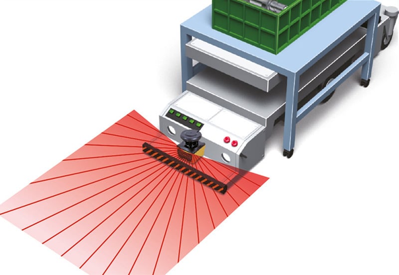
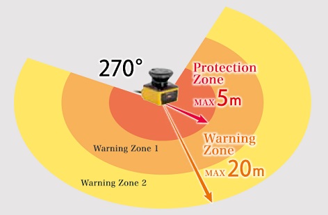
This is where safety laser scanners come in. These scanning units are versatile, programmable, and feature many interesting capabilities not shared by safety light curtains. Safety laser scanners, such as the UAM scanner from Hokuyo, project an arc of lasers from a central point, and have a 270 degree field of vision. The UAM scanner features a total of 3 programmable outputs. The innermost field, which can be up to 5 metres in radius, is the distance at which a safety output will occur. The two outermost fields can be up to a total of 20 metres in radius, and act as the two warning areas.
What makes laser scanners particularly interesting is what lies in their programmability. While custom radii is helpful, what is even more helpful is that laser scanner protection areas can be drawn into various shapes, sizes, and are not limited to just circular shapes. Using UAM project designer, UAM series safety laser scanners can be programmed, monitored, and customised to the wishes and requirements of the user.
Safety laser scanners are versatile tools in industrial safety, and are commonly called upon in applications where flexible, 2D-area monitoring is required. These scanners are particularly useful in settings where machinery or personnel must be safeguarded across various zones, or can be warned as they approach an imminent hazard. Safety laser scanners are highly flexible, making them a great addition for oddly-shaped hazardous areas.
Laser scanners are great for warning zones around robotic arms, automated guided vehicles (AGVs), and complex automated machinery. In contrast, a safety light curtain is ideal for creating physical boundaries that prevent access to specific hazardous zones within manufacturing cells.
When it comes to other ground based proximity detection, safety mats such as offerings from ASO are another option to factor in. They are more rigid and simple in design, and will save the tedious task of wiring. Their warning zones – so to speak – are certainly more definite, and the protection area they offer is always rectangular and thus more difficult to customise. When it comes to large areas that require often differing levels of protection, a laser scanner becomes the more affordable and sensible option
| Laser Scanners | Light Curtains | Safety Mats | |
|---|---|---|---|
| Flexibility | Highly flexible, suitable for complex zones | Best suited for straightforward, linear zones | Most affordable for small, rectangular areas |
| Detection Area | Wide and configurable 2D-area coverage | Limited to a specific barrier or plane | Limited to rectangular shapes, but can be used in series to cover larger area |
| Installation | Requires strategic placement but fewer units | Typically simpler setup in fixed-line protection | Extremely simple, 2-wire or 4-wire configurations with end resistors |
| Applications | Ideal for AGVs, robotics, and conveyors | Effective for guarding machine entry/exit points | Effective for guarding fixed areas that are not subject so change |
| Drawbacks | Sensitive to environmental interference | Limited to straight-line or framed protection | Limited to square areas, and can become less cost-effective as the area increases |
Operational Steps – Setting Up a Hokuyo UAM Scanner
1. Introduction
This demonstrative instructional is a generic guide on how to set up a Hokuyo UAM-05LP-T301 Safety Laser Scanner. These configurations will be to control 3 LEDs on a lamp, and a safety contactor. The lamp has a green, orange, and red LED. When nothing is detected, all 3 LEDs will be illuminated. 1 protection zone and 2 warning zones will be configured. Each zone is roughly 15 centimetres long, and of a trapezoidal shape. The innermost zone will control the green LED, along with deenergising the solenoid inside the safety contactor, disconnecting power to any theoretical machinery. The middle warning zone will control the on/off state of the yellow LED, while the outermost warning zone will toggle the red LED. The scanner will be powered by a 24VDC power supply, and in this configuration bypasses any need for a safety relay. For this setup you will need:
1. Jumper wires
2. Small flathead screwdriver
3. A laptop with the Hokuyo UAM Project Designer software (Download Here)
4. A micro USB cable (for programming/upload)
5. Your output devices (we used a 3 colour lamp)
6. A 24 Volts DC power supply
7. A Hokuyo UAM-05LP-T301 Laser Scanner
8. A safety contactor
2. Wiring Configuration A
| Colour | Signal | Function | Description | AWG |
|---|---|---|---|---|
| Brown | +24V DC | Power | Power Supply: DC 24V | 22 |
| Blue | 0V DC | Power | Power Supply: 0V | 22 |
| Red | OSSD1 | Output | Protection zone output 1 | 26 |
| Yellow | OSSD2 | Output | Protection zone output 2 | 26 |
| Red/Black | Warning 1/OSSD3 | Output | Warning zone output 1/Protection zone output 3 | 28 |
| Yellow/Black | Warning 2/OSSD4 | Output | Warning zone output 2/Protection zone output 4 | 28 |
| Purple | IN_A | Input | Area switching input A | 28 |
| Grey | IN_B/Muting 3 | Input | Area switching input B/Muting input 3 | 28 |
| White | IN_C/Override 1/ENC1_A | Input | Area switching input C/Override input 1/Encoder input 1A | 28 |
| Pink | IN_D/Muting 1/ENC1_B | Input | Area switching input D/Muting input 1/Encoder input 1B | 28 |
| Green | IN_E/EDM1 | Input | Area switching input E/External device monitoring 1 | 28 |
| Purple/Black | IN_A | Input | Area switching input A | 28 |
| Grey/Black | IN_B/Muting 4 | Input | Area switching input B/Muting input 4 | 28 |
| White/Black | IN_C/Override 2/ENC2_A | Input | Area switching input C invert/Override input 2/Encoder input 2A | 28 |
| Pink/Black | IN_D/Muting 2/ENC2_B | Input | Area switching input D invert/Muting input 2/Encoder input 2B | 28 |
| Green/Black | IN_EDM2 | Input | Area switching input E invert/External device monitoring 2 | 28 |
| Yellow/Green | RESET 1 | Input | Reset 1 | 28 |
| Yellow/Blue | RESET 2 | Input | Reset 2 | 28 |
| Orange | RES_REQ 1/MUT_OUT1 | Output | RES_REQ 1: Request output 1/MUT_OUT1: Muting state output 1 | 28 |
| Orange/Black | RES_REQ 2/MUT_OUT2 | Output | RES_REQ 2: Request output 2/MUT_OUT2: Muting state output 2 | 28 |
| White/Blue (TP) | RS485+ | Communication | Communication Protocol RS485 | 28 |
| White/Red (TP) | RS485- | Communication | Communication Protocol RS485 | 28 |
| Shield Wire | FG | — | Frame Ground | — |
3. Wiring Configuration B
For the application of controlling 3 lights, 2 for the warning zones and 1 for the safety output, we connected:
- Brown wire of scanner to 24 Volts DC
- Blue wire of scanner to 0 Volts DC
- Red wire of scanner to A1 of the safety contactor (this is the protection zone/OSSD1/2)
- Red/Black wire of scanner to red LED
- Yellow/Black wire of scanner to orange LED
- Yellow/Green wire of scanner to 24 Volts DC via a normally open switch (this is for MANUAL RESET)
- Orange wire of scanner to 0 Volts DC (this is for RESET REQUEST)
- Green wire of LED to 24 Volts DC via the normally open auxiliary contacts of the safety contactor.
4. UAM Project Designer
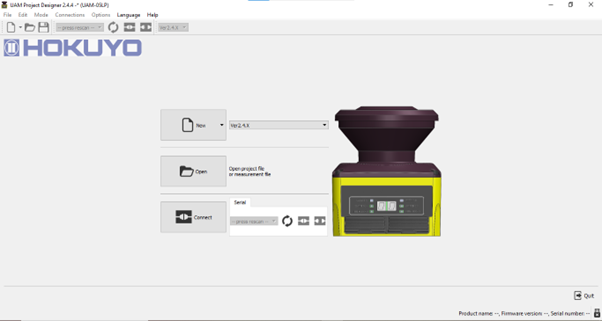
Step 1. Open UAM Project Designer and connect to the scanner plugged in via micro USB. Make a new project.
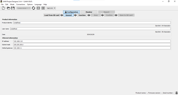
Step 2. Name your project file accordingly
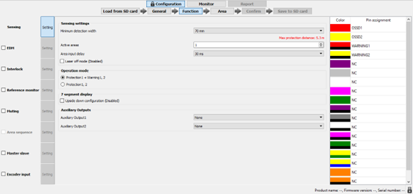
Step 3. This is the functions page, this allows you to setup specific and useful functions, but will not be needed for this basic demonstration.
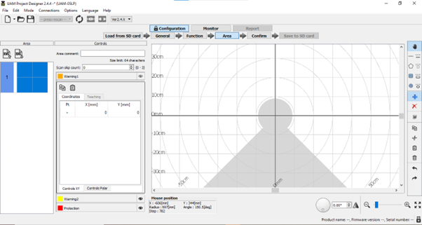
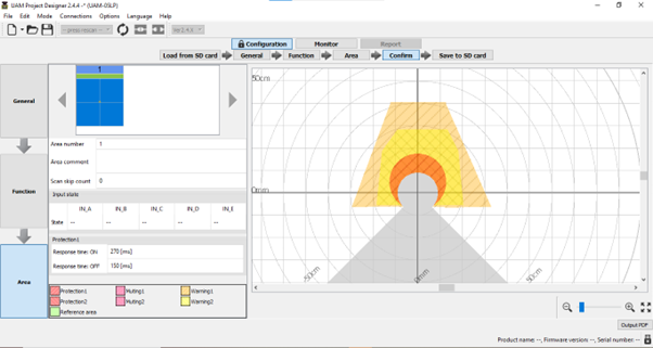
Step 4. This is the page where you will draw your protection zones. You also have the option to drag and drop basic shapes as your starting point for these zones.
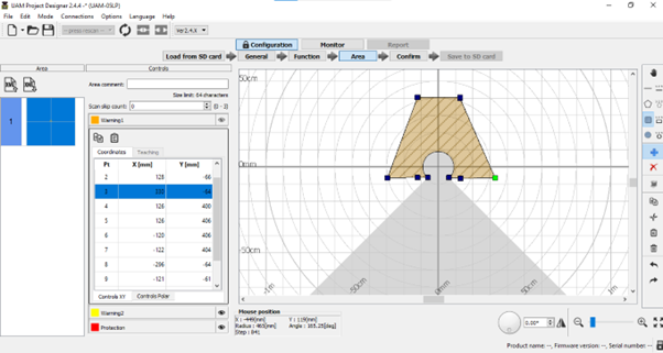
Step 5. Drag and drop/draw your protection zone shape. This can be selected as OSSD1/2
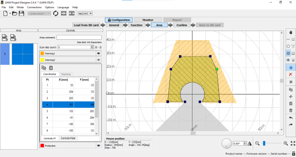
Step 6. Draw or drag and drop your first warning zone shape. This will be WARN1
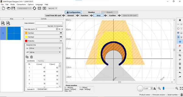
Step 7. Draw or drag and drop your second warning zone shape. This will be WARN2
Step 8. This is the finalised shape ready to be uploaded to the scanner. This can by pressing the button 5th from the left in the upper functions bar
5. Testing Video
Specifications of Hokuyo Safety Laser Scanners
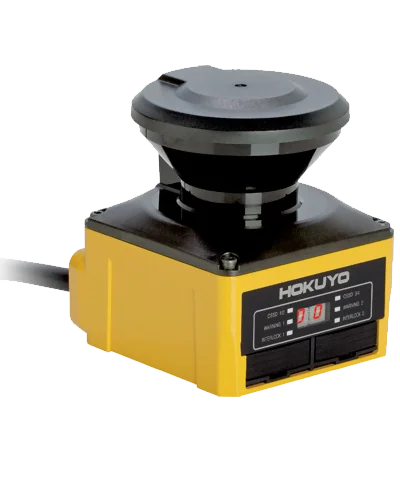
Hokuyo’s UAM series scanners are two of the smallest safety laser scanners available on the market, and are greatly useful for automated processes, and are great for not only safety, but also for boundary conditions given to automated guided vehicles (AGVs). The UAM-05LP-T301 is offered with two cabling formats. The standard UAM-05LP-T301 is provided with large, 3 metre long wire with 23 smaller internal wires. On the other hand, the UAM-05LP-T301C variant comes with a standardised connector at its end. Removing the need for an overwhelming amount of cabling, and sporting a waterproof connector, the UAM-05LP-T301C comes with a 0.3 metre long cable with a standardised M12 sized connector. The M12 connector is bound to simplify some of the full capabilities of the 23-wire variant; but if features such as area switching, or the maximum of 32 individual areas are not needed, then the M12 connector version can simplify the normally tedious task of wiring and setup.
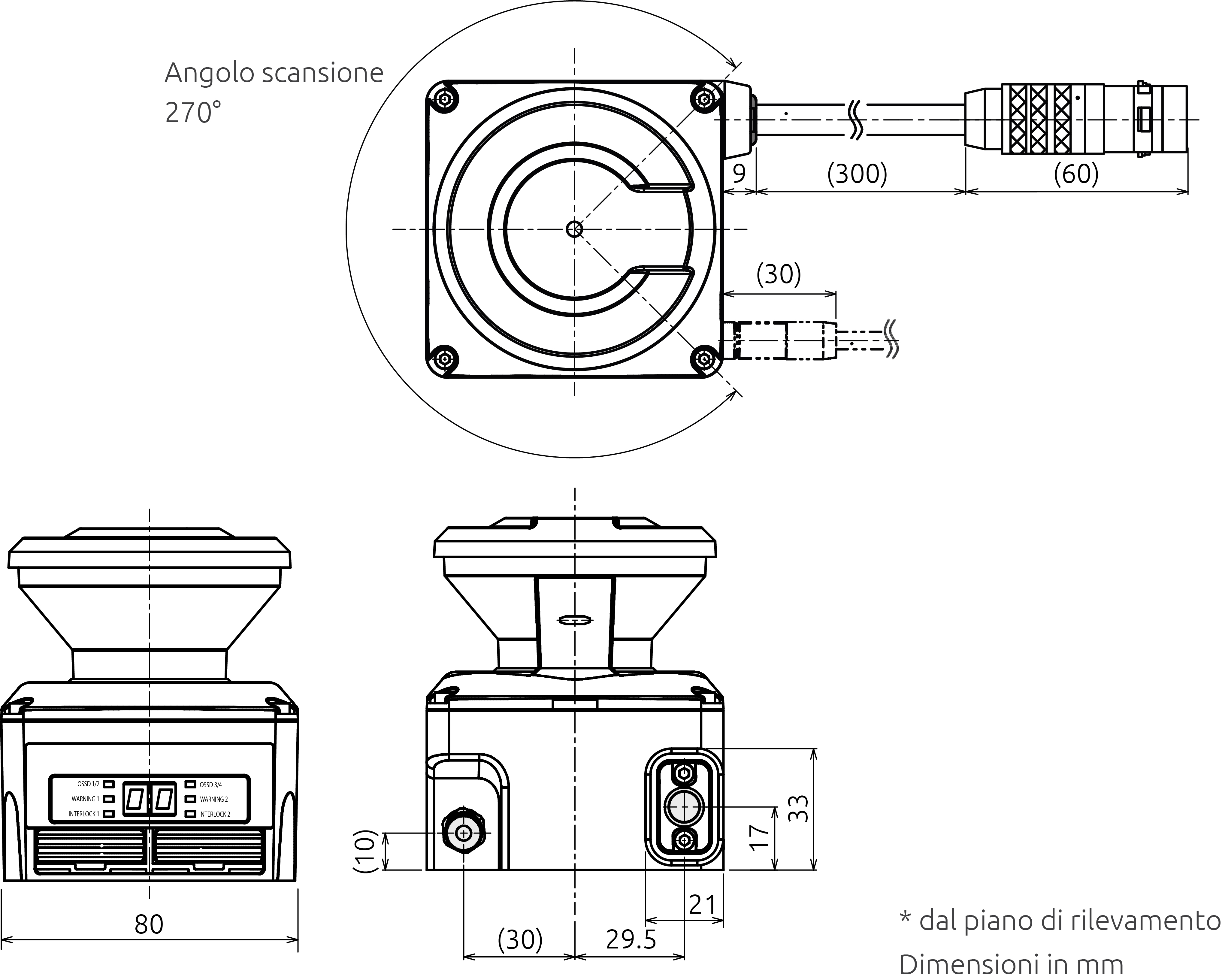
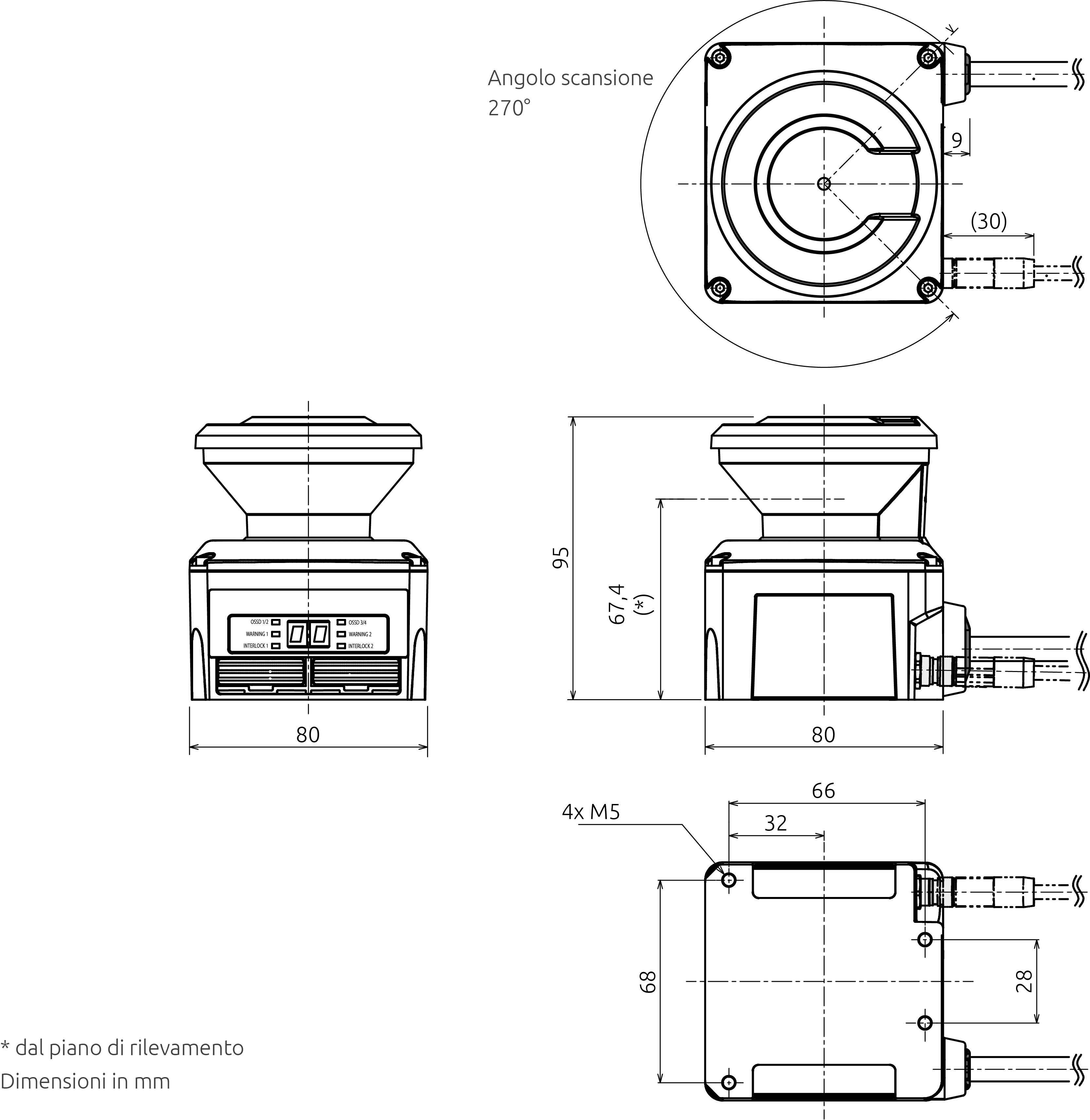
Protection Range: Max 5 metres
Warning Range: Max 20 metres (non-safety)
Distance Tolerance: +100 mm
Detection Capabilities: From black-reflector sheet (1.8%) to retro-reflector sheet
Detection Range: 270°
Scanning Frequency: 30ms (Rotational Speed of 2000rpm).
Area Pattern: Max 32 patterns
Wavelength: 905nm
- Cable length: 3 metres, 23 wires OR 0.3 metres, M12 connector
- Power Supply (converter): DC 24V ±10%
- Power Supply (battery): DC 24V -30%/+20%
- Supply Power (without load): 6 Watts
- Supply Power (with load): 50 Watts
OSSD1/2 Current: 500mA
OSSD3/4 Current: 250mA
Warning 1/2 Current: 250mA
RES_REQ 1/2 Output Current: 200mA
MUT_OUT 1/2 Output Current: 200mA
Input Impedance: 4.7 kΩ
TUV SUD:
Type 3 (IEC61496-3)
SIL2 (IEC 61508 Part 1-7:2010, EN 62061:2005/A1: 2013)
Category 3, PL d (EN ISO13849-1:2015)
Safety of laser products Class 1 (IEC60825-1:2007)
Case Material (Body): Aluminium
Case Material (Optical Window): Polycarbonate
Other Safety Input Devices
While light curtains and safety mats have been discussed in comparison in this article, Venus Automation also supplies a number of alternative safety inputs, to suit a variety of industrial applications. For example, to detect presence or motion at close range, proximity sensors are available, including non-contact switches, with magnetic or RFID coding technologies. Enclosures come in plastic, metal, or stainless steel variants for application-specific durability. If the machine is protected my physical guarding which must stay locked while in operation, then interlock devices such as tongue solenoid interlock switch or electro-magnetic switches would be highly effective. For a consolidated interface, multifunctional gatebox units are available.
Additionally, specialised light curtains are available that are optimised for smaller areas, such as hand protection and finger protection. Supporting components such as photo cells, connection boxes, and muting accessories are also supplied. Similarly, products derived from the safety mat such as safety edge systems, bumpers, and relevant edge accessories. Manual control inputs are also critical in many safety scenarios. Venus Automation provides safety enabling switches, limit switch options, foot pedal switches, control pads, and standard control components. For advanced zone control, trapped key systems and blocking devices ensure that machinery cannot be accessed without fully disengaging power.
Compatible Relays and PLCs
While safety laser scanners are highly effective, the safe deactivation of the machine is dependent on the control logic system used.
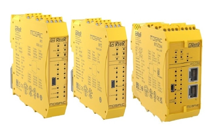
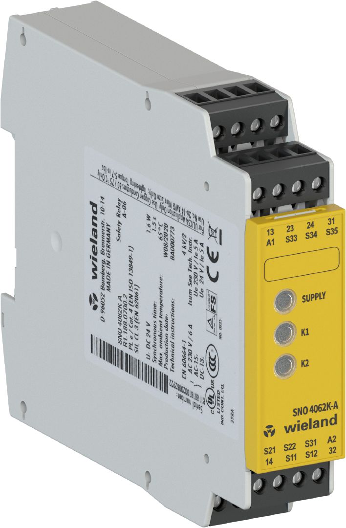
The main form of control logic in modern safety systems is the safety PLC. These programmable devices allow custom safety logic, with flexible input/output terminal assignments. Venus Automation offers a variety of models, including the MOSAIC PLC from ReeR, Samos PLC from Wieland, and GEMNIS PLC from Pizzato—each delivering advanced and reliable safety functionality.
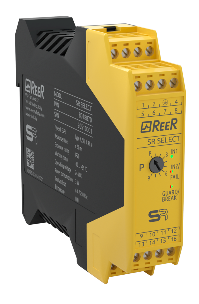
Where complex programmability is unnecessary, alternative options such as safety relays are available. These include standalone relays, time-delay relays, speed-monitoring relays, standstill monitoring and timer relays, PCB relays and relay expansion modules. These options provide effective and application-specific safety responses, and are also compatible with safety laser scanners.
Conclusion
Safety laser scanners have revolutionized industrial safety by providing flexible, programmable, and highly efficient protection for hazardous zones. Unlike traditional safety light curtains, which are limited to detecting objects in a single plane, laser scanners cover a wide, configurable area, making them ideal for applications requiring multi-directional detection.
These scanners are particularly valuable in environments with autonomous machinery, such as AGVs and robotic arms, where precise safety zoning is critical. By using configurable warning and safety fields, safety laser scanners can slow down or stop machines when someone approaches, providing an additional layer of proactive accident prevention.
Compared to safety mats, which require direct physical contact to trigger a response, laser scanners provide non-contact protection, reducing wear and maintenance costs. Additionally, advanced features like muting allow for intelligent monitoring, ensuring workflow efficiency without compromising safety.
By integrating laser scanners into your safety system, you enhance workplace security, improve operational efficiency, and comply with stringent industry regulations. Investing in the right safety technology today ensures a safer, smarter, and more productive work environment.
.png)