11
A Theoretical Site Visit and Plant Assessment
CESE-level Risk Assessments
Here at Venus Automation, our goals lie within maximising safety, compliance, and reliability for our clientele. Aside from the remote and on-site technical support and advice we provide, we also offer risk assessments of factories, machinery, and assembly lines. So, what does this look like? A risk assessment is broken up into sections, where one of our engineers takes a sequential approach in analysing the risks and hazards that present themselves on a worksite. Safety and risk requirements can be broken up into an index of Performance Level (PL), where risks are analysed based on their severity, frequency, and possibility of occurrence.
Risk Assessments through Venus Automation are highly technical and are carried out by a Certified Electrical Safety Engineer, or CESE. CESE is a course/certification offered by Wieland; a company we work closely with as their Australian licensed distributor for electrical goods. This certification is globally recognised by SGS TÜV Saar, and covers the functional safety aspects of machinery with a focus on programmable electrical, electronic, and electro-mechanical aspects.
Venus Automation offers risk assessments that are compliant with the training provided through the CESE certification, and is thus an operation that ensures that your factory machinery is legal, compliant, and most importantly, as safe as possible for operators and machinery alike.
This blog is an informative guide walking through how a risk assessment provided by a certified engineer such as this. This risk assessment comprises two machine lines that were assessed, where issues were found with a number of safety input devices, and power supply and connectivity methods. This blog post covers the corrections/suggestions that have been made to bring the safety rating of these devices up, and ensure that the plant machinery is compliant with safety standards, and Work Health and Safety Legislations and Acts.
The Hypothetical Plant & problematic devices – Introduction
For this theoretical exercise, it will be simulated that a total of seven different devices/situations that were found to not be of satisfactory compliance during this risk assessment. A brief outline of what these devices are has been listed below, with each of these problems – and their solutions – being discussed in their own sections on this post.
- A single, non-safety contactor has been used, and operating current sometimes exceeds the contactor’s rated current.
- All of the emergency stops for a machine are wired in single channels into a safety relay.
- Upon checking with a multimeter, it has been found that the 24 Volt power supply sometimes drops to 20 Volts.
- Some of the machinery is connected via junction boxes, but this machinery has been propositioned to move between sides of the factory.
- The emergency stop currently uses automatic reset, but operators require it to be manual reset.
- There is a magnetic safety switch being used on a gate that requires locking, but it is intermittent in functionality and is not secure enough.
- There is no mechanical interlock being used on a gate that needs to be locked during hazardous machine operation.
Safety Contactors – requirements vs reality
Introduction
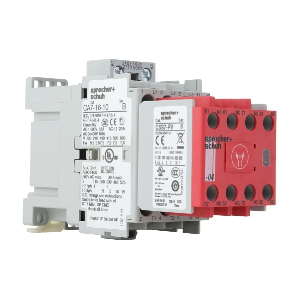
Contactors are a vital part of connecting industrial machinery to 3 phase electricity. They receive power from relays when certain conditions are met; and when energised, a solenoid (a coil that acts as an electromagnet) is powered, and the contacts inside of it are pulled shut. Only when the contacts are shut will 3 phase power flow through the contactor and into the machinery that requires the electricity. Contactors can either be non-safety rated or safety rated. Safety-rated contactors come with auxiliary contact blocks: a set of usually 4 normally open or closed contacts that will change when the open/closed status of the contactor toggles. These can be used for feedback loops, which feed into the reset inputs of safety relays or safety PLCs for the safe monitoring of the status of the contactor. When set up correctly (safely), safety contactor feedback loops will enable fault conditions to be met and cause the discontinuation of machine operation. Safety contactors are often placed in series to one another so that in the event of a contactor failing (which is discussed in potential hazards), the contactors will still be able to cut power to hazardous machinery.
Contactors become unsafe when they fail, and it is crucial that the machinery they power—and thus their respective power and current requirements—is suited to the ratings of what the contactor is capable of handling. Contactors can either be powering alternating current (AC) electrics or a 24V power supply.
Example: Safety Rated vs non-Safety Rated Contactors
A Sprecher + Schuh Safety Rated, 7.5kw Contactor

A Sprecher + Schuch Non-Safety Rated, 7.5kw Contactor
What we found
During the plant assessment, analysis of the electrical panel revealed that there was one, non-safety rated contactor being used to provide 3 phase 415 Volt electricity to a 7.5 kilowatt, 12 Amp AC motor used in the plant. The contactor was rated for an amperage of 13 Amps, and a power maximum of 11 kilowatts. However, it was found that as the motor has aged, it has started drawing more and more amperage from the wall; so despite being equipped to handle the power requirements of the motor, the maximum current rating of the contactor is now exceeded by the current drawn by the motor. What this means is that the contactor is now at risk of failure due to exceeded current draw.
Potential Hazards
Due to their being only one contactor, if this contactor were to fail closed, there would be nothing preventing continuous flow of electricity from the grid to the motor; it would continue to operate indefinitely besides the main isolation switch. Additionally, the contactor that was used had no auxiliary contacts, which means that feedback (confirmation that contactor had opened or closed) could not be monitored by a safety relay if required, although this isn’t helpful in the non-redundant single contactor system.
When amperage is exceeded beyond a contactor’s current rating, excess heat is generated and the normally open switches that are pulled shut by the energised solenoid can become welded shut. This means that power can flow continuously through the contactor, and cannot be stopped.
How to achieve Category 4 (best) Safety Rating
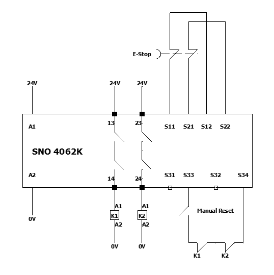
To achieve a Category 4 safety rating with contactors, Venus Automation recommended that the single contactor be replaced with two, safety rated contactors wired in series. By wiring the contactors in series, 3 phase power now has two conditions to pass through before making its way to driving the motor. By using two contactors, there is now an extra redundancy, this means that if a contactor welds shut, power can still be disconnected, and the motor can be safely stopped. Furthermore, the use of safety rated contactors not only means the components themselves meet safety requirements, but the auxiliary contacts on each of the safety contactors can be connected to a feedback loop. The feedback wiring can pass through each of the contactors’ normally closed auxiliary contacts, a normally open switch (the manual reset button), and then into the reset input of a safety relay. If one of the contactor auxiliary blocks is open while the other is closed (i.e. a contactor has been welded), the feedback loop will be broken and cause a short. The contactor can then safely stop via e-stop, but cannot be restarted due to a fault condition being met.
Testing Video
(https://youtu.be/lK337B2oFNY)
Wiring Diagram
Emergency Stops – Single vs Dual Channel
Product Examples:

Emergency Stop Head
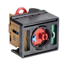
Rear view of E-stop head and contact block
Emergency stops (often called E-stops) are input devices monitored by safety relays used to disconnect power to output devices. They are prominent components in industrial workspaces and are used to halt most machinery in the case of an emergency.
Visually speaking, emergency stops are as simple as a button that is easily visible and easily pressed; they lock into place once they are pressed in and need to be twisted, pulled, and reset to resume functionality. These buttons are found around most industrial machinery, and their status is monitored via safety relays using one or two channels.
Emergency stops, while visually being just a button, rely on a series of normally open and normally closed contacts to operate correctly when actuated. Generally speaking, E-stops have two normally closed contact blocks that are actuated upon pressing the button.
The image below depicts the ring in which an E-stop head can be fitted. The middle two contacts are normally closed and are opened when the E-stop button is triggered. The blue switch simply detects the presence of an E-stop button head, while the green normally open switch can be used as an auxiliary contact for needs like illumination when pressed, etc.
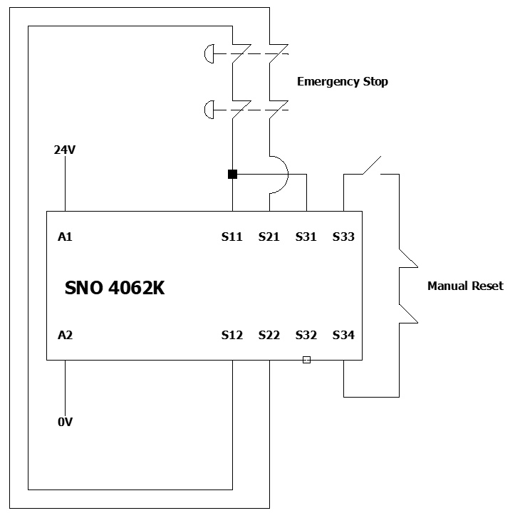
The two normally closed contacts are generally used for monitoring via a safety relay. On a Wieland SNO 4062K, for example, one normally closed contact would separate safety inputs S11 and S12—this would be single-channel. If you wanted to use the second channel, you can either split S11 through two contact blocks, or you can use a second set of safety inputs on the relay. For example, S11-S12 could be connected via the first normally closed contact, while S21-S22 could be connected via the second normally closed contact. Now, two safety input channels on the relay are monitoring the E-stop.
Upon pressing an E-stop, two normally closed contacts open, and the circuit is broken. The relay then sees that safety inputs are no longer being received, which is used as a condition to control the on/off state of a contactor and thus the devices being driven.
However, in the case of what was found during our risk assessment, all of the emergency stops being used at this plant were only single channel. This means that if there were ever a short, the E-stops would not be able to actuate the motors/contactors and stop hazardous operations.
The best way to achieve Category 4 of safety when it comes to E-stops is to occupy two available channels of a safety relay with the safety inputs given by the normally closed contacts of an E-stop. By using two, parallel channels, there is now inbuilt redundancy regarding the safety inputs of the E-stop. The relay can now cross-monitor the emergency stop contacts, and throw fault codes/halt machinery when it sees any faults occur. This ensures that machinery can still safely stop even when wiring issues occur.
Power Supplies – Fixing Faults
Introduction to 24 Volt DC Power Supplies
While most large industrial machinery – especially AC motors – are driven by 415V AC electrics, there are still some critical devices, especially those used for safety input and logic, that are powered by 24-volt power supplies. To ensure that power supplies still meet the specifications they are manufactured to, these power supplies need to be regularly checked, making sure that their outputs are not irregular.
From Shortcomings to Shorts
Upon inspection of the power supply used at this plant, a multimeter was employed to check that the voltage output of the power supply was still 24 volts. The multimeter revealed that during idle conditions, a strong, 23.9-volt signal was read. However, during startup of the contactors and motors, the voltage would sometimes deviate to as low as 20 volts. This is not acceptable, and an aging power supply could eventuate in power loss to critical safety devices such as relays and the devices connected to them like emergency stops.
Mitigation/Replacement
To maintain the safety and consistency of power delivery to 24-volt components inside the electrical panel of this machine, the power supply was replaced with a new 24-volt power supply, and a multimeter was once again employed to ensure that the issue was indeed the power supply. Upon verifying that the old power supply was the issue, this was another mitigation that was easily made via replacement.
Multimeter Testing Video
From Junction Boxes to Connector Plugs
The cabling for both power and signal within this plant was predominantly connected and routed via junction boxes. While this is not exactly problematic, the foreman electrician of the plant had stated that this machine, depending on the flow of the factory during that day and what machinery was predominantly being used on a given day. Junction boxes, while completely functional and suitable for stable machinery that is immobile, is not particularly modular. They use screw or clamp terminals, and are often tedious to disassemble and move, and thus not very modular.
Recommendations were made to the plant electricians that they convert their 24 wire junction boxes into plugs using Wieland revos connectors. Connectors from the revos line use inserts anywhere between 5 and 48 poles to allow for modular assembly, disassembly, and routing throughout industrial environments.
What is beneficial about the revos connectors is that they have now been standardised and made more universal, meaning that any plug connectors they may use down the line – whether they be revos branded or not – will still work with preexisting plugs.
The overall increased modularity and flexibility granted by converting from junction boxes to connectors and plugs, which will save electricians the time and hassle involved with tediously wiring and disconnecting junction boxes. The electricians have taken this step to modernise the electrical routing within the factory.
Wieland revos basic connector/plug configuration
Although initial migration from junction boxes to revos plugs and connectors is tedious, and can lead to the inevitable downtime of machinery, once everything is up and running again, the use of plug connectors like Wieland revos will save the headache of wiring clamp and screw terminal junction boxes. They can be used for not only power cabling, but also signal wiring – making them very flexible. Overall, Wieland revos connectors future proof the infrastructure of power and control signal routing throughout industrial factories.
Automatic vs Manual reset – using pushbuttons
Reset/startup Relay function
While both automatic and manual reset are fine for Category 4 emergency stops, manual reset tends to be the more commonplace method for resetting E-stops in industry. The difference between them is that machine operation can resume immediately after the E-stop is pulled out during automatic reset – which will reduce wiring and enhance the immediacy by which operations can resume. However, in cases where there needs to be a delay or a deliberate human decision/discretion to resume operations, it is important that an extra step be taken to ensure that this can happen. This is where manual resets come in, wherein an extra normally open contact used in the reset loop (or feedback loop) is used. Even when the E-stop has been pulled out, the normally open contact (generally attached to a standard non-safety button) needs to be depressed to allow for a pulse to travel through the feedback loop, allowing for the machinery to resume operation.
Reset and startup is a pulse signal that is received by safety relays. There are dedicated inputs on safety relays that expect just one high voltage pulse to interpret that startup/reset is permitted. In the case of some relays, you can simply bridge two inputs together and this will enable automatic reset. In others, specific pins need to be bridged depending on if you want automatic or manual reset. In the case of relays such as offerings from DOLD, there are sometimes dip switches or dials on the relay used to select different conditions for automatic and manual reset.
What we found/Required Changes
It was found that all the E-stops and switches were on automatic reset, which was no longer desired by the operators. While it was convenient during the initial setup of these machinery, scenarios falsely considered as safe had injured workers in the past due to pulling the E-stop out immediately. Now, they wish to migrate to manual reset, but did not have any buttons to facilitate a change in reset functionality. One step taken that was easy, however, was simply moving the channel for automatic reset over into the manual reset bridge set.
When implementing manual reset buttons, it is important that they are placed in areas that optimise concious and safe decision making from machine operators. Reset switches must be placed within direct view of the hazardous area, meaning that operators are inclined to assess the hazardous area and confirm that it is clear before they reset the machine.
New Infrastructure
All of the original enclosures for the existing emergency stops were found to not have the cutouts to supplement new, manual reset buttons. So the infrastructure required involved getting new enclosures with cutouts for the E-stop, with another cutout for an illuminated pushbutton.
These pushbuttons connected to a normally open contact block and were wired into the reset channels of the relay. Now, the E-stops were capable of resetting manually and were in upgraded enclosures to facilitate manual reset pushbuttons.
Non-Contact Safety Switches, and the need for Safety Interlocks
Non-Contact safety switches are a safety input device used mainly for doors, gates, and guards that actuate. They rely on either magnetic or RFID communication technology to energize/de-energize, which then signals safety relays whether the gate is open or closed. This safety input for monitoring the state of a door—particularly if it provides access to a hazard—can then be used as a logical condition on whether a machine should be permitted to operate or not.
For a long time, magnetic switches have been an affordable option that made sense to implement. They are straightforward to wire and cost-effective if they ever need replacing. Magnetic safety switches are limited in actuation/direction, and it is possible to trick them with another magnet into believing the gate/door is closed when it is not. If a machine is relying on a switch to read as closed to operate and is tricked into believing the door is closed, then a person could potentially access a hazard with the safety system being none the wiser.
To circumvent the problems presented by magnetic non-contact switches regarding security and directional limitations, RFID switches have been introduced as new non-contact switches. RFID switches work in an identical fashion and achieve the same end results as magnetic switches, but instead use radio frequency identification methods for increased security (RFID has a unique address, making it much harder to trick). Furthermore, RFID switches can actuate in several directions, making them well-suited for multidimensional, hinged, and sliding gates, which can quite easily implement these switches with no directional limitations.
Non-contact safety switches are a powerful tool for monitoring guards, gates, and other moving/actuating areas around machinery. However, safety switches cannot be relied on entirely to safeguard workers from accessing hazardous machinery. Non-contact safety switches, in situations such as this, should really only ever be used to monitor the open/closed state of a door. To reinforce this and increase the number of conditions required to open a gate/disable a machine, some form of mechanical interlock is required.
Mechanical interlocks, like safety switches, are a safety input that can be used as conditional logic for safety relays. They reinforce the capabilities of non-contact switches by introducing a mechanical and electric means to keep a door shut during machine operation. Mechanical interlocks best suited for the gates such as the ones presented during the risk assessment are tongue solenoid, and trapped key interlocks.
Tongue solenoid interlocks are a form of safety switch that incorporates mechanical safeguarding into gates opening and closing. Rather than relying on an electromagnetic lock, a solenoid interlock utilises the presence of a physical ‘tongue’ (think an insert into a receiver) to register a safe signal and thus allow the machine to operate.
Safety switches such as the NG series from Pizzato incorporate BOTH RFID and a tongue insert to actuate. This creates an in-built redundancy for registering if a door is open or not. The door now not only needs to be closed but also needs to be locked to send a signal to the machine that it is okay to operate. This extra redundancy is what allows these Pizzato switches to be classified as Category 4.
A Pizzato NG Solenoid Interlock
Trapped key interlocks are an additional, unique, and almost entirely mechanical solution to opening passageways. They may require some form of power signal to release the key, or may actually be used to send a power signal if and only if the key is in place. Trapped Key interlocks, such as offerings from Fortress, are a unique way of securing access points, while ensuring that no one can restart the machine without the presence of a key. So, a maintenance worker could take the key from the gate, walk into the restricted area, and the machine could never start until the key is present, and the door is locked.
A Fortress Trapped-Key System
Other Forms of Safety Input: Light Curtains & Safety Edge
While not the subject of this blog, two common alternative safety inputs to those discussed are also of interest: light curtains and contact detection systems. Safety Light Curtains operate by sending infrared beams and detecting if these are blocked, creating a detection screen between their emitter and receiver, with spacing of beams differing between light curtains for body protection, hand protection, and finger protection. Other variants supporting long range sensing and outdoor environments are available, along with muting light curtain models designed for automated processes. Supporting components such as photo cells, connection boxes, and muting accessories are also stocked. Additionally, other similar products are available, including multi beam systems and advanced laser scanner technologies.
Contact detection is supported by products such as safety edge and mounting systems, contact mats, and bumpers with relevant edge accessories. These are ideal for perimeter and surface-triggered protection zones, where machine guarding is impractical (hence eliminating ability to use non-contact switches and physical interlocks) and light curtains would be unwieldy to install.
Conclusion
Ensuring industrial safety requires a comprehensive approach that integrates multiple layers of protection. From the critical role of emergency stops, which provide an immediate means to halt dangerous operations, to the importance of contact blocks that facilitate reliable electrical connections, every component plays a vital role. Efficient wiring and system organization are also key, which is why transitioning from traditional enclosures to modular junction boxes enhances flexibility and maintenance efficiency.
Additionally, adopting high-performance Revos connectors ensures a robust and standardized approach to electrical connections, reducing downtime and improving overall system reliability. Meanwhile, modern non-contact safety switches offer advanced protection for doors, gates, and access points, minimizing risks while maintaining seamless workflow automation.
By integrating these solutions, industries can create safer work environments, streamline operations, and ensure compliance with stringent safety standards. Investing in these technologies is not just about protection—it’s about fostering efficiency and sustainability in industrial automation.


