Whether you’re managing servo motors in CNC or automation systems, refurbishing legacy drive modules, or designing new architectures, this guide covers essential aspects: closed-loop control…
Whether you’re managing servo motors in CNC or automation systems, refurbishing legacy drive modules, or designing new architectures, this guide covers essential aspects: closed-loop control strategies, feedback devices, speed control techniques, power supply design, control loop architecture, diagnostics, and migration planning. Our aim is to provide you with content that supports robust, reliable, and precision motor control in industrial automation and control systems across Australia.
Fundamentals: How Servo Drives, Controllers & Feedback Devices Work
Drive, Controller & Feedback Signal in the Control System
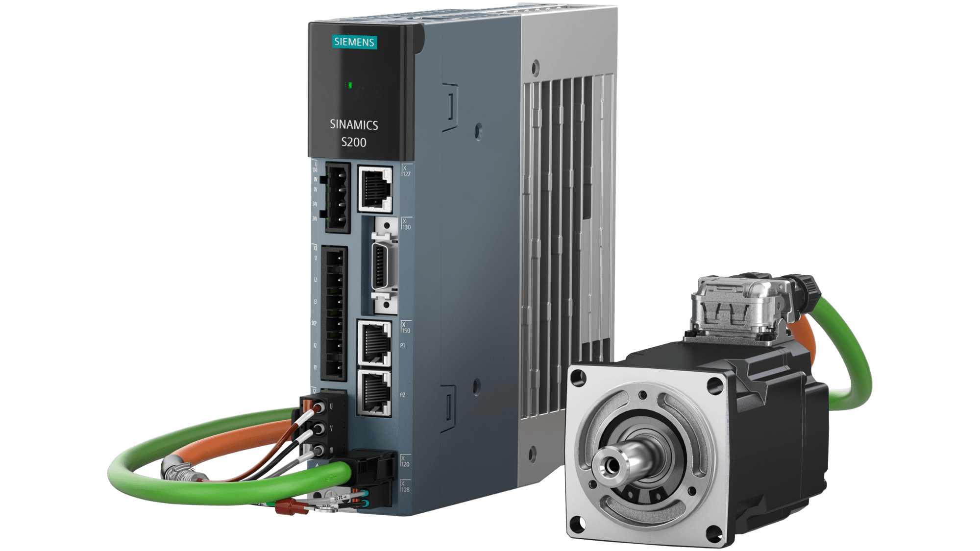
In every modern control system, the servo controller (or motion controller) issues motion commands—position profiles, velocity targets, or torque limits. The servo drive, sometimes called a servo amplifier, receives these command signals and delivers the appropriate current and voltage to drive servo motors. Meanwhile, a feedback device (such as an encoder, resolver, or optical sensor) sends back a feedback signal indicating the actual position, speed, or torque. The drive compares that feedback signal with the commanded value and applies corrections in real time through closed-loop control.
This architecture underpins motion control systems and enables accurate speed control, position regulation, and rapid response to load disturbances. Without feedback, systems degenerate into open-loop behavior, losing accuracy and adaptability.
Servo drives constantly monitor feedback, adjusting outputs to reduce errors—a capability described thoroughly in standard references.
The Importance of Closed-Loop Control
Closed-loop systems offer self-correction: any deviation between desired and actual output is detected via feedback and corrected immediately. This mechanism allows systems to maintain precision even under external disturbances and variable load conditions. In contrast, open-loop control lacks this error correction—errors accumulate, and stability suffers.
In servo architectures, nested control loops handle multiple levels of correction:
- The position loop aligns the system to the commanded position
- The velocity loop governs speed trajectories
- The current/torque loop manages instantaneous load dynamics
Such cascaded loops (often implemented using PID or advanced control algorithms) are central to stable speed control and accurate motion.
Design & Performance Considerations
Power Supply & Current Matching
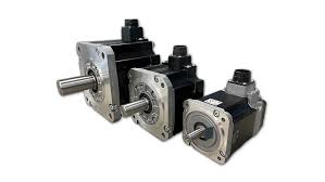
A well-designed power supply is critical: it must deliver both peak demands and stable continuous current. Voltage sag or instability in supply can lead to faults or system drift. The drive must be matched to the motor’s voltage and current ratings—whether driving standard servo motors, linear motors, or hybrid configurations incorporating DC motors.
Feedback Devices & Signal Integrity
Feedback devices—such as incremental encoders, absolute encoders, optical sensors, or resolvers—generate the feedback signal that drives error correction. The quality of resolution, signal noise, jitter, and latency all influence system stability. Poor feedback signal integrity degrades position feedback and impairs performance.
Control Loop & Algorithm Strategy
Motion systems typically use a three-tiered approach: position, velocity, and current loops, each running a control algorithm (often PID, sometimes state-feedback or adaptive control).
- Position control ensures the system reaches desired locations
- Velocity control shapes acceleration and deceleration profiles
- Current (torque) loop handles rapid load transients
Correct tuning is crucial to achieve responsive, stable behavior and reduce overshoot or oscillation. Studies exploring control strategies (including PID variations, state-feedback, and optimized controllers) confirm that advanced methods outperform classical controls in challenging environments.
Regeneration, Thermal Protection & Robustness
During deceleration, energy must be handled safely—either through regenerative circuits or external braking resistors. Servo drives include protections (overcurrent, overvoltage, thermal) to safeguard long-term reliability. Robust design ensures durability even in harsh operating conditions or after decades of service.
Matching Motor & Amplifier
In systems using brushless or DC motors, matching amplifier switching frequency, inductance, torque constants, and feedback is vital to avoid performance issues. A well-known application note emphasizes how mismatches degrade torque ripple, efficiency, and dynamic performance.
Applications, Diagnostics & Integration
Industrial Use Cases & Legacy Systems
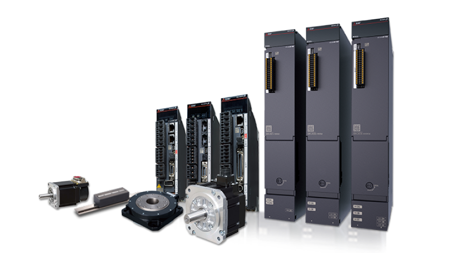
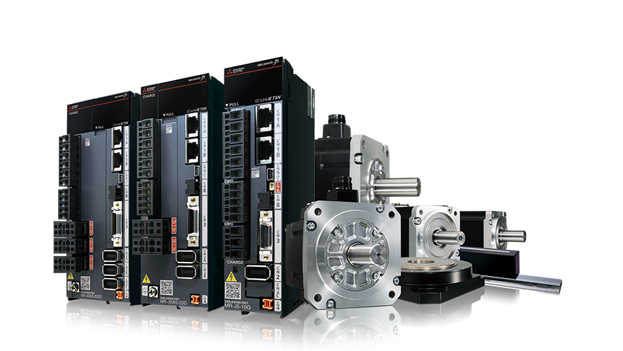
Servo drives and controllers are pervasive in industrial automation, CNC machines, robotics, packaging, and precision equipment. Many installations rely on legacy servo amplifiers or drives with discontinued firmware. Migrating or refurbishing these systems requires careful planning: ensuring compatibility of feedback devices, control loops, interfaces, and diagnostics.
Troubleshooting & Diagnostics
Common troubleshooting techniques include:
- Verifying feedback signal wiring, grounding, and shielding
- Substituting known-good drives or controllers to isolate faults
- Monitoring drive diagnostics for overtemperature, overcurrent, or communication errors
- Testing under load to verify speed control and position accuracy
These steps simplify fault isolation between motor, drive, feedback, or control components.
Migration Strategies & Upgrading
When modernizing legacy systems:
- Use cross-reference tools to map legacy servo amplifier or drive models
- Assure compatibility of feedback protocols, control system architecture, and communication interfaces
- Retune control loops using step or test input stimuli
- Validate performance across all operational conditions
Integration with broader automation systems (PLCs, motion controllers, HMI) often requires attention to network protocols (Modbus RTU, EtherCAT, etc.), synchronization, and safety system coordination.
Safety, Motion & System Integration
Servo systems rarely operate in isolation—they must integrate with safety and automation architectures. Servo drives, motors, and controllers often partner with safety controllers or safety PLCs to deliver features like Safe Torque Off (STO), fault monitoring, and emergency shutdown.
Peripheral safety devices—such as E-stop relays, two-hand stations, solenoid locking switches, and interlocks—feed into the safety logic. Meanwhile, servo systems integrate standstill monitors, current-monitoring relays, and measurement light curtains to detect anomalies. Power relays, regulated power supplies, voltage monitoring, and phase sequence detection systems support stable operation. Data collected is displayed on HMIs or management systems for operator visibility and system health monitoring.
Open-Loop vs Closed-Loop Control in Servo Systems
Open-Loop Control Overview
Open-loop control drives motors without feedback. Common in stepper motor systems or simple control tasks, it lacks self-correction—the system blindly follows commands without measuring actual output. Errors accumulate, especially under variable load or mechanical play.
Closed-Loop Control System
Closed-loop control uses feedback to continuously correct deviations. This mechanism is foundational for servo systems, enabling accuracy, stability, and dynamic response. For example, a cruise control in a car is a classic servo system—it adjusts throttle based on speed feedback.
Some systems use semi-closed approaches, but full closed-loop architectures offer the highest precision and performance in demanding motion control environments.
Advanced Control & Emerging Trends
Research in control theory is pushing servo systems toward smarter, more robust techniques. Approaches like model-free adaptive control, internal model control, and layered robust schemes allow systems to cope with nonlinearities and load disturbances without detailed plant models.
Multi-axis motion controllers and synchronized trajectory platforms enable coherent, high-throughput motion across multiple servo drives. Coupled with improved sensors and processing power, future architectures promise even tighter control, faster dynamics, and smarter diagnostics.
FAQ
Q: What differentiates a servo drive from a servo controller?
A: The servo controller handles trajectory planning, logic, and system-level coordination, while the servo drive executes the fast inner control loops using feedback signals to control current and voltage.
Q: Why is closed-loop control superior to open-loop?
A: Closed-loop systems detect and correct errors continuously, yielding greater precision, stability, and load compensation than open-loop systems.
Q: What role do feedback devices play?
A: They provide the feedback signal (position, speed, torque) to the drive, enabling error correction and high-fidelity control.
Q: Can legacy servo amplifiers be reused?
A: Yes—provided you can support firmware, feedback protocol compatibility, and correct tuning of control loops.
Call to Action
Have a servo drive, amplifier, controller, or legacy module to repair, replace, or integrate? Contact us with the model, system specs, and desired performance. Our engineers assist with cross-referencing, loop tuning, migration strategy, and system restoration in your automation environment.